IC card with radio interface function, antenna module and data processing apparatus using the IC card
a radio interface and function technology, applied in the direction of sensing by electromagnetic radiation, coupling device connection, instruments, etc., can solve the problems of no conventional sd memory card of a small size that installs a radio interface function, and is smaller than the pc card,
- Summary
- Abstract
- Description
- Claims
- Application Information
AI Technical Summary
Benefits of technology
Problems solved by technology
Method used
Image
Examples
first embodiment
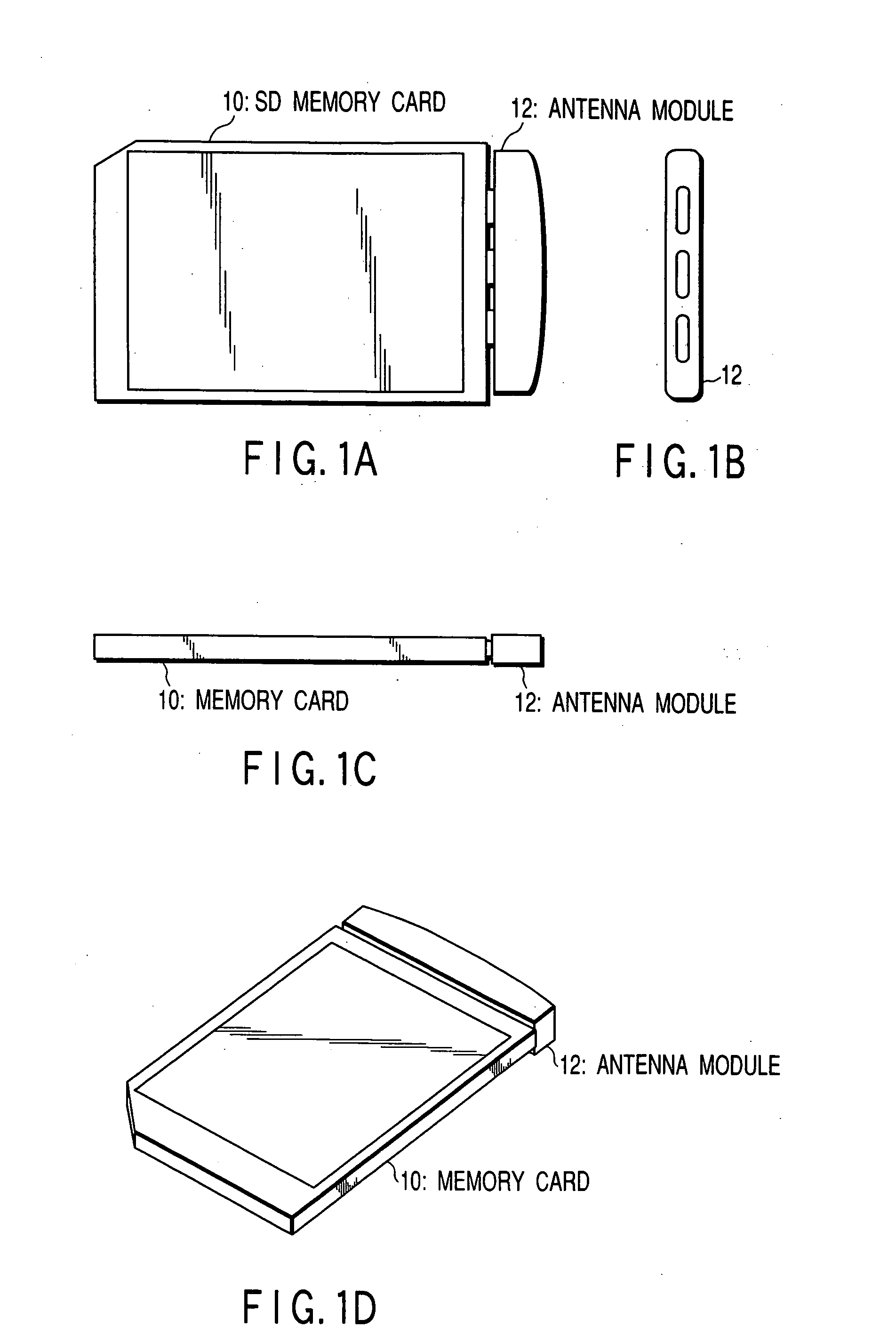
[0032] The SD memory card 10 shown in FIGS. 1A-1D, will be described.
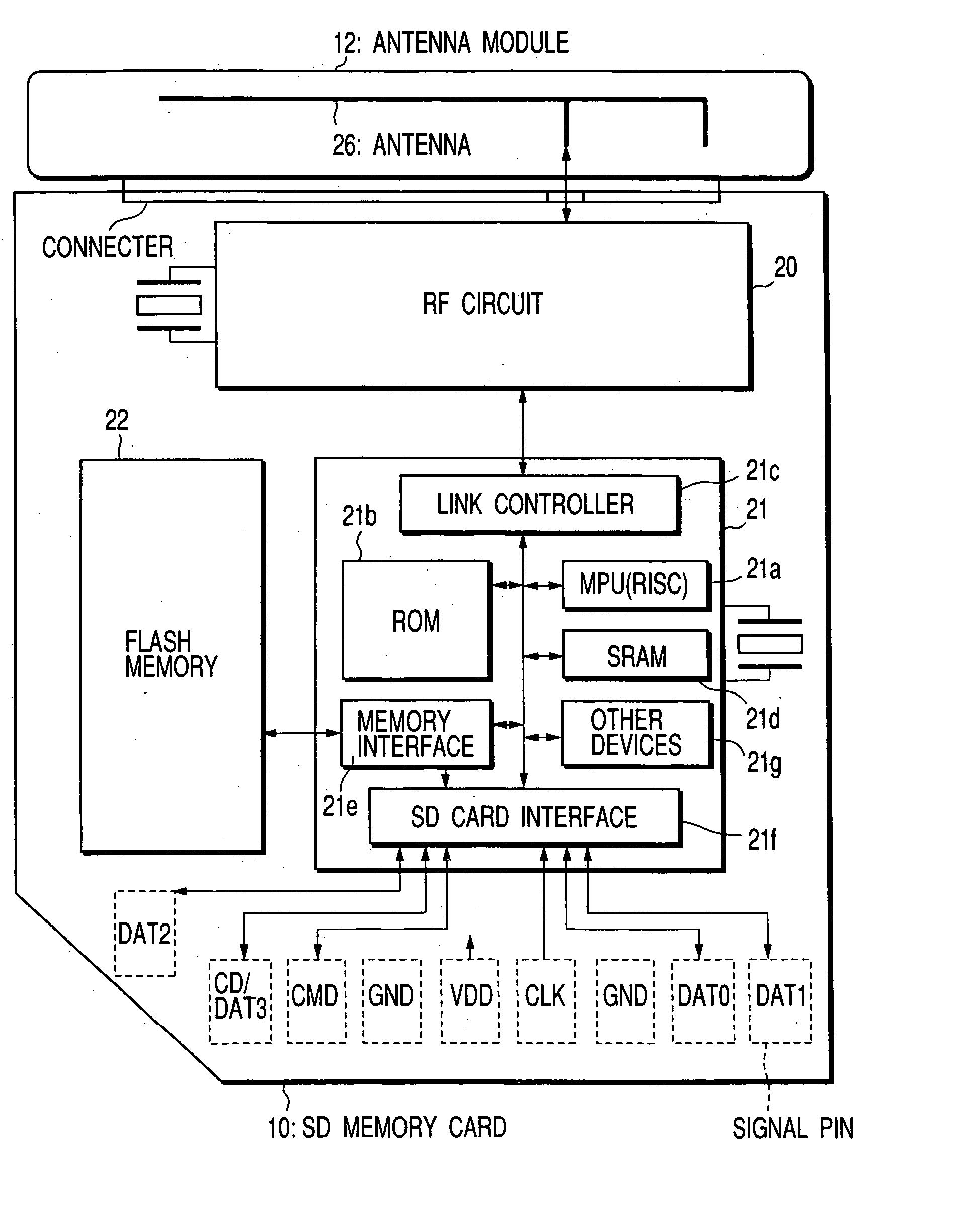
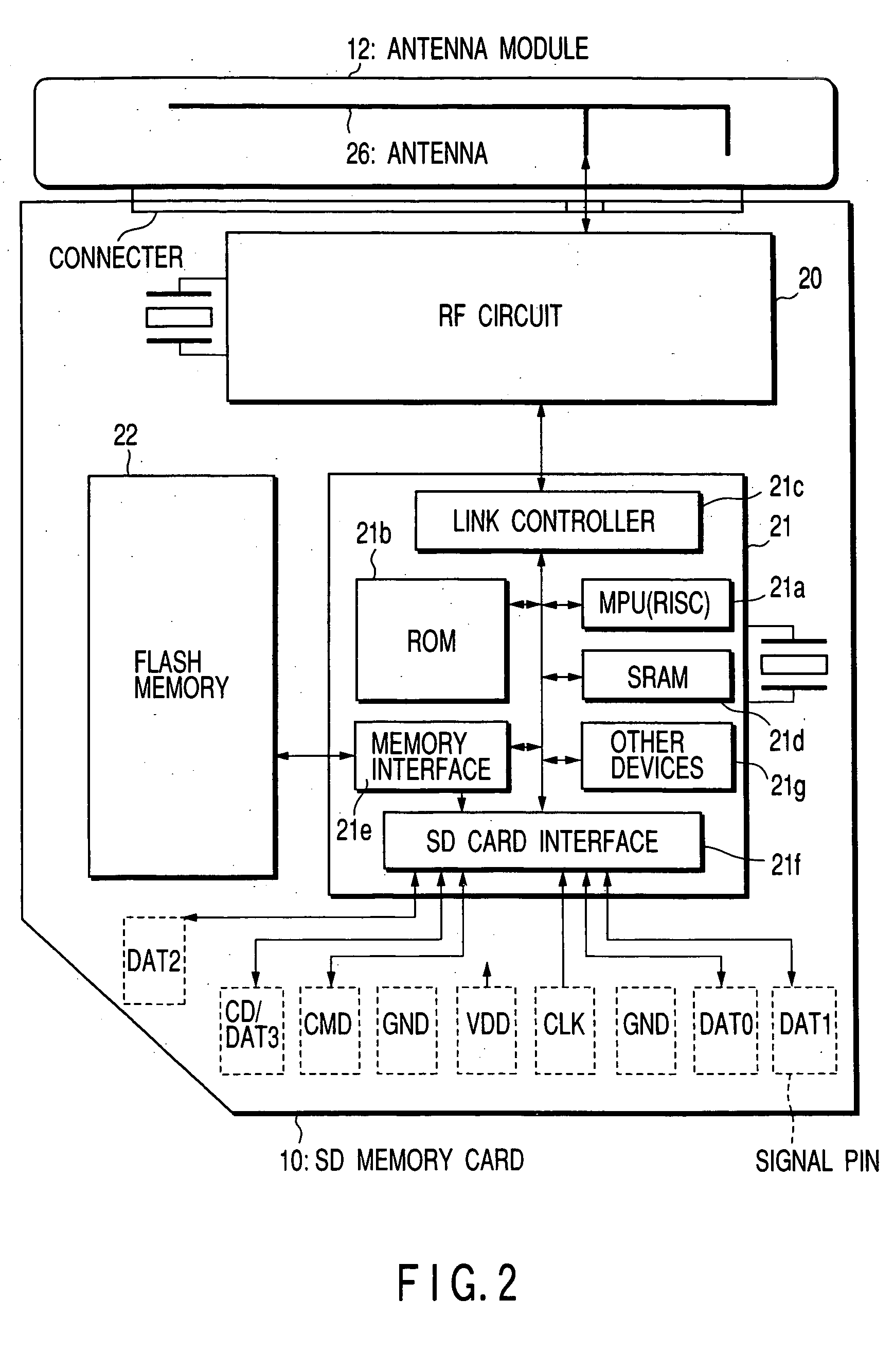
[0033]FIG. 2 is a block diagram illustrating the SD memory card 10 and the antenna module 12 shown in FIGS. 1A-1D and employed in the first embodiment of the invention. Suppose that the SD memory card 10 of the first embodiment has a radio interface function and uses Bluetooth as a radio communication system.
[0034] Bluetooth is the short-distance radio-communication standard, which implements radio communication within a radius of approx. 10 m using 2.45-GHz band. In Bluetooth, the frequency hopping method is used as spectrum diffusion techniques and enables up to eight devices to be connected by time-division multiplexing. In Bluetooth, the devices connected by time-division multiplexing constitute a network called Piconet, where one device functions as a parent device and the other devices function as child devices. In the network (Piconet), connection is certified using a code number called PIN (personal Ident...
second embodiment
[0046] An SD memory card 10c will be described.
[0047]FIG. 4 is a block diagram illustrating the SD memory card 10c and an antenna module 12 employed in the second embodiment. The SD memory card 10c of the second embodiment differs in the antenna mounting structure from the SD memory card 10 of the first embodiment (shown in FIG. 2 or 3). As shown in FIG. 4, an antenna A27 is provided in the SD memory card 10c along the side of the card on which no signal pins are provided, and is connected to an RF circuit 20. The antenna module 12 can be attached to the SD memory card 10c as in the first embodiment (a connector for attachment is not shown in FIG. 4). When the antenna module 12 is attached to the SD memory card 10c, an antenna B28 for Bluetooth provided in the antenna module 12 is connected to the RF circuit 20 via an antenna connector. The other structural elements are similar to those employed in the first embodiment (FIG. 2), and hence not described.
[0048] Provision of the ante...
third embodiment
[0053] An SD memory card 10d will be described.
[0054]FIG. 5 is a block diagram illustrating the SD memory card 10d and an antenna module 12a employed in the third embodiment. The antenna module 12a of the third embodiment has, in addition to the antenna B28 employed in the second embodiment (FIG. 4), an external RF amplifier 29 that serves as part of a high frequency circuit (high frequency amplifier).
[0055] Specifically, as shown in FIG. 5, the antenna module 12a contains the internal antenna B28 for Bluetooth, and the external RF amplifier 29. When the antenna module 12a is attached to the SD memory card 10d, the antenna B28 is connected to the RF circuit 20 of the card 10d via the external RF amplifier 29 and an antenna connector. The other structural elements are similar to those employed in the first embodiment (FIG. 2), and hence not described.
[0056] The external RF amplifier 29 amplifies a radio signal transmitted or received by the antenna B28.
[0057] Accordingly, the att...
PUM
 Abstract
Description
Claims
Application Information
 - R&D
- Intellectual Property
- Life Sciences
- Materials
- Tech Scout
- Unparalleled Data Quality
- Higher Quality Content
- 60% Fewer Hallucinations
Browse by: Latest US Patents, China's latest patents, Technical Efficacy Thesaurus, Application Domain, Technology Topic, Popular Technical Reports.
© 2025 PatSnap. All rights reserved.Legal|Privacy policy|Modern Slavery Act Transparency Statement|Sitemap|About US| Contact US: help@patsnap.com


