
Method of dynamic transmit scheduling using channel quality feedback

a dynamic transmit and channel technology, applied in the field of communication systems, can solve the problems of maximizing system capacity when high data rate channels are active, maintaining a high data rate connection at a required fixed error rate,

Inactive Publication Date: 2005-01-06
GOOGLE TECH HLDG LLC
View PDF38 Cites 49 Cited by
  • Summary
  • Abstract
  • Description
  • Claims
  • Application Information

AI Technical Summary

Problems solved by technology

One problem associated with the combination of voice, packet data, and circuit data services operating concurrently is the ability to maintain a high data rate connection at a required fixed error rate over a channel of varying quality.
In addition, maximizing system capacity when high data rate channels are active presents another problem.

Method used


Image

  • Method of dynamic transmit scheduling using channel quality feedback
  • Method of dynamic transmit scheduling using channel quality feedback
  • Method of dynamic transmit scheduling using channel quality feedback

Examples


Embodiment Construction

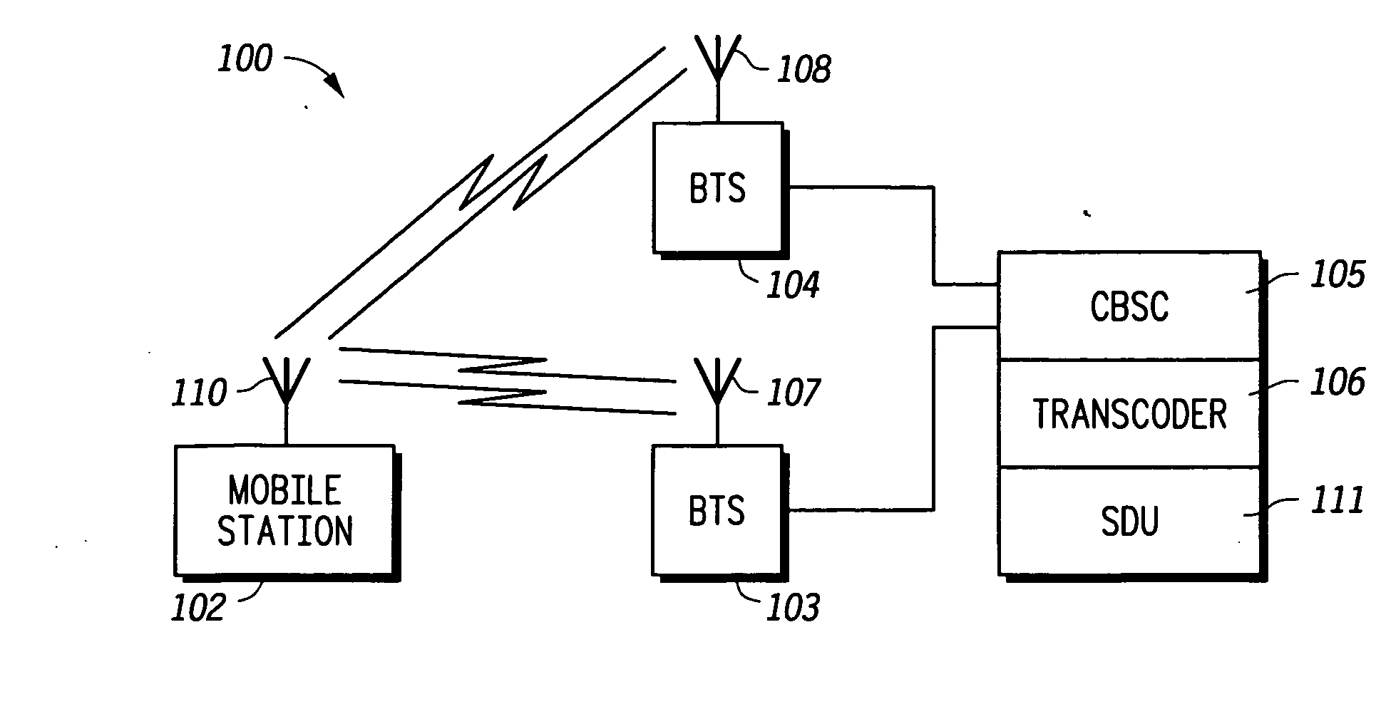
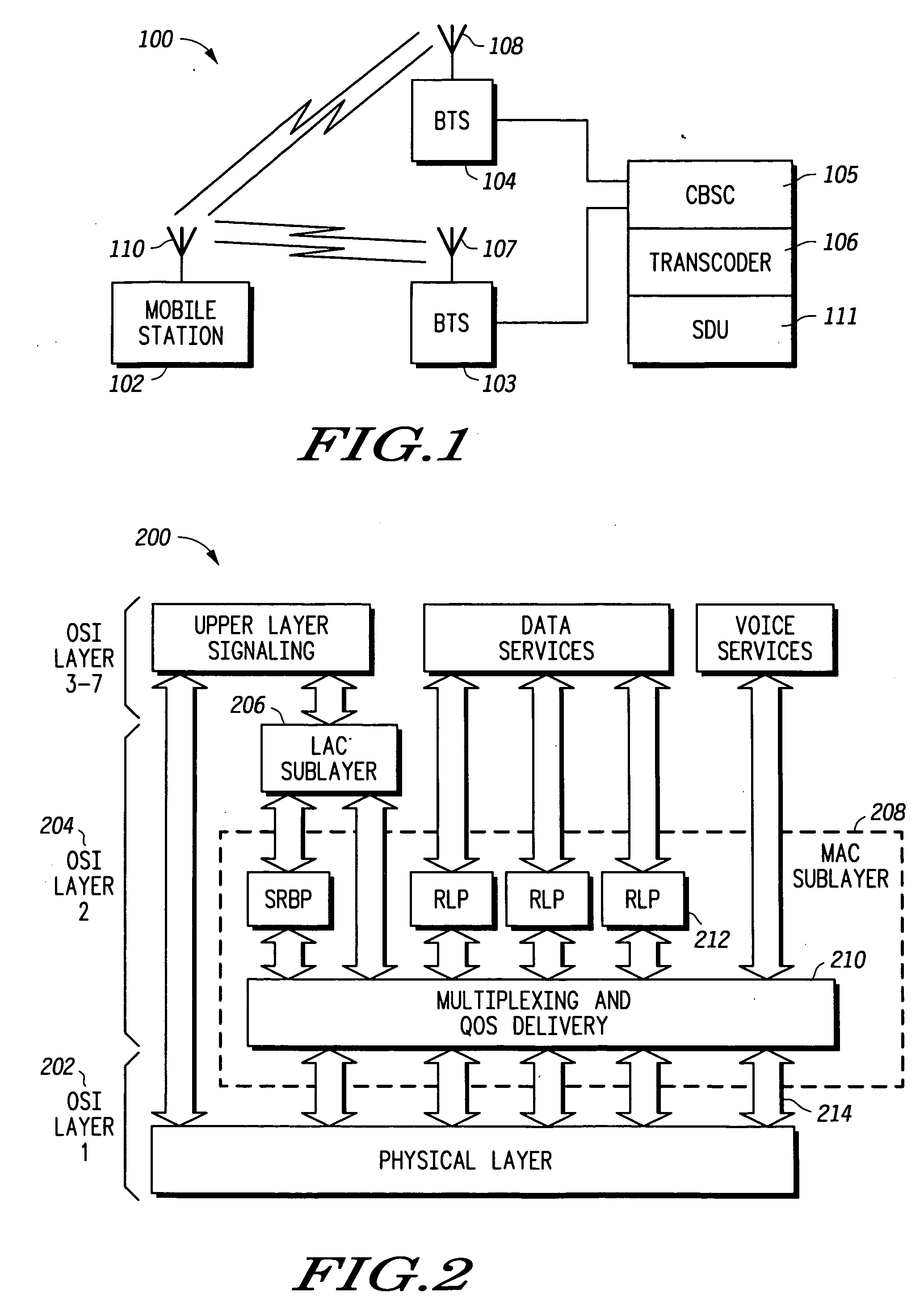
[0016]FIG. 1 depicts a communication system 100 in accordance with the preferred embodiment of the present invention. System100 includes a mobile station 102, a first base transceiver station 104, a second base transceiver station 103, and a Centralized Base Station Controller (CBSC) 105. CBSC 105 includes a transcoder 106, and a selection distribution unit 111. System 100 preferably includes a plurality of mobile stations and base transceiver stations, but only one mobile station and two base transceiver stations are depicted in FIG. 1 for clarity. In a preferred embodiment, system 100 is a Code Division Multiple Access (CDMA) system. System 100 may also be any communication system that transmits signaling messages and requires accurate delivery and receipt by mobile stations.

[0017] First base station 104 includes a transceiver 108 that includes a transmitter and a receiver. Second base station 103 includes a transceiver 107 that includes a transmitter and a receiver. Transceivers...


PUM


Abstract

A method and system for dynamic rate switching via medium access channel layer signaling is disclosed, wherein data rates for high data rate channels are automatically shifted up or down based on a predetermined metric. In a preferred embodiment, data rates are automatically shifted up or down based on transmit channel gain required to maintain a required signal to noise ratio.

Description

FIELD OF THE INVENTION [0001] The present invention is related in general to communication systems, and, more particularly, to an improved method and system for dynamic scheduling via channel quality feedback. BACKGROUND OF THE INVENTION [0002] Standards bodies such as the International Standards Organization (ISO) have adopted a layered approach for the reference model of a communication subsystem. The complete communication subsystem is broken down into a number of layers, each of which performs a well-defined function in the context of the overall communication subsystem. It operates according to a defined protocol by exchanging messages, both user data and additional control information, with a corresponding peer layer in a remote system. Each layer has a well-defined interface between itself and the layer immediately above and below. Consequently, the implementation of a particular protocol layer is independent of all other layers. The function of each layer is specified formal...

Claims


Application Information

Patent Timeline
Patent Type & Authority Applications(United States)
IPC IPC(8): H04B7/005H04B17/00H04B7/26H04L12/56H04W28/22H04W52/22H04W72/12
CPCH04W28/22H04W52/221H04B17/24H04W72/1284H04W72/1231H04W72/542H04W72/21
Inventor LOVE, ROBERT T.ROTSTEIN, RONCUDAK, MARK C.CLASSON, BRIAN
Owner GOOGLE TECH HLDG LLC
Learn More