Fastening device for an electrical device

a technology for mounting devices and electrical devices, which is applied in the direction of lighting support devices, electrical apparatus casings/cabinets/drawers, washstands, etc., and can solve problems such as high vibration load in operation

Inactive Publication Date: 2004-12-30
ROBERT BOSCH GMBH
View PDF7 Cites 3 Cited by
  • Summary
  • Abstract
  • Description
  • Claims
  • Application Information

AI Technical Summary

Benefits of technology

[0003] A mounting device for an electrical unit, having at least one mounting element which is anchored to the part that supports the electrical unit and in the housing of the electrical unit, is advantageously further embodied according to the invention in that a matching geometric distribution of the devices for receiving the mounting elements is made on the housing and on the parts that support the housing, in such a way that the devices on the unit, in the installation position, each face some of the devices on the supporting part.[0004] With the invention, mounting concepts for motor vehicle control units for instance can be realized in a simple and economical way in a modular system, since control units with various embodiments, for instance in a tight or nontight design and in various sizes can be connected to the vehicle by way of the same mechanical interface. Because the mounting device is located inside the housing contour of the unit, customer-specific installation dimensions can easily be adhered to. Because the mounting points are made uniform regardless of the embodiment of the control unit, with always the same bore spacings, the same screw dome heights, and the same kinds of screws, for instance, as mounting elements, there is no need to have a large number of different variant mountings.[0005] It is also advantageous if the devices on the housing are screw-in domes, into which self-tapping screws, as mounting elements, can be screwed. By way of such screw-on points, it is additionally possible for instance for the lost heat that must be dissipated from the housing to be carried away, which has a favorable effect on the mounting location and on the performance of the unit.[0006] It is also advantageous if in a housing for an electrical control or regulating unit for an electromechanical or electronic assembly in a motor vehicle, the circuit elements of the control unit, in particular the printed circuit board, are retained on the housing with fasteners that are separate from the mounting elements for the attachment to the supporting parts. According to the invention, the clamping mechanism in the interior of the housing and having the printed circuit board of the circuit arrangement remains untouched by vibration loads fed in via the separate mounting device, and as a result the vibration strength of the unit is improved.[0007] The final assembly of the electrical unit can advantageously be done before the assembly of any other angle brackets that may be needed, so that once again considerable expense for tool holders can be eliminated. Thus an overall cost reduction from the simplified development and testing of the housings can be achieved, and lower production costs arise because of the reduction in the number of parts, because flexible standard mounting concepts that suit many customers are employed and because of the lower setup costs for what is overall a simplified apparatus.

Problems solved by technology

For that purpose, suitable angle brackets are typically secured to the electrical unit via the clamping mechanism of the printed circuit board on the one hand and on the other to the supporting parts in the motor vehicle, such as assemblies or sheet-metal parts of the auto body, which can lead to a high vibration load in operation.

Method used


Image

  • Fastening device for an electrical device
  • Fastening device for an electrical device
  • Fastening device for an electrical device

Examples


Embodiment Construction

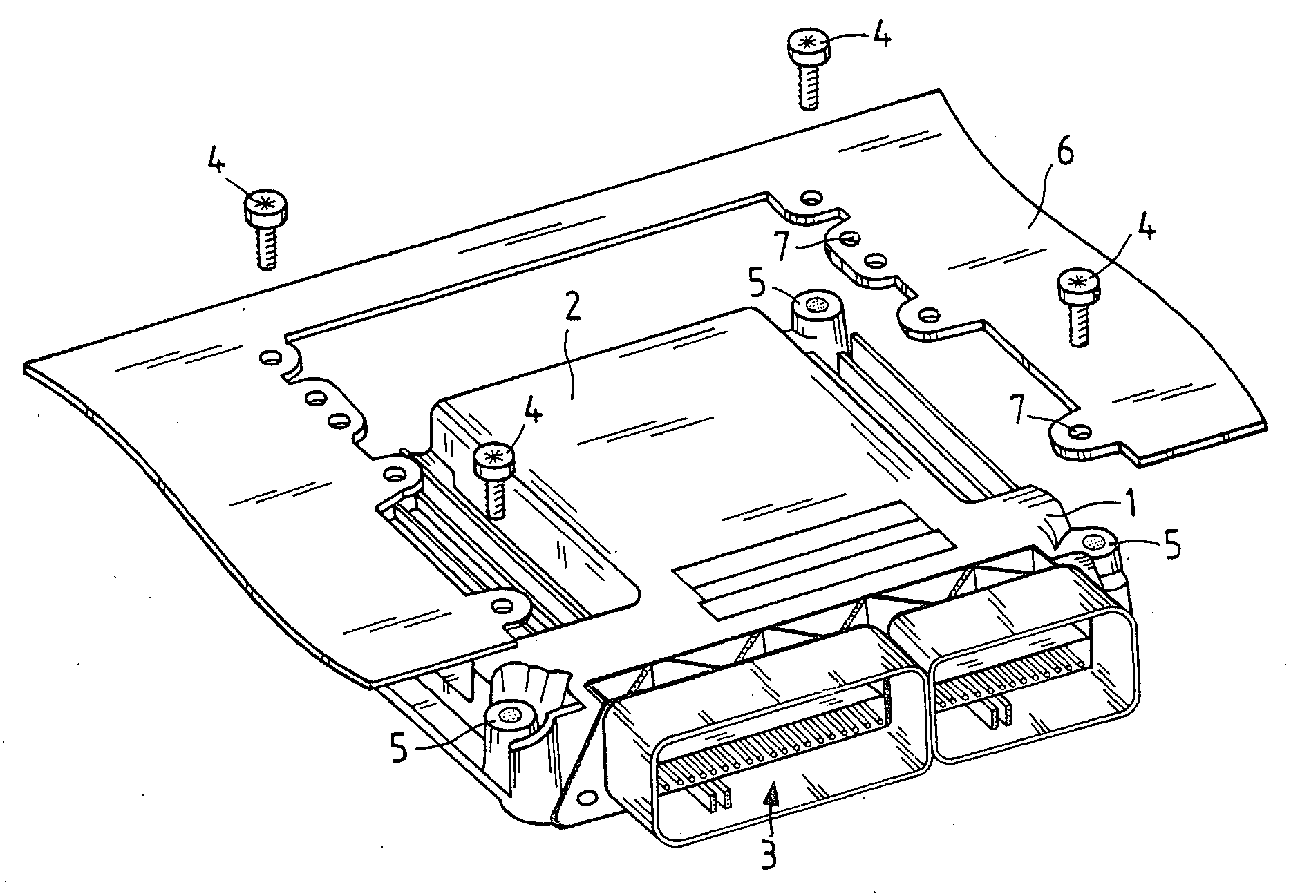
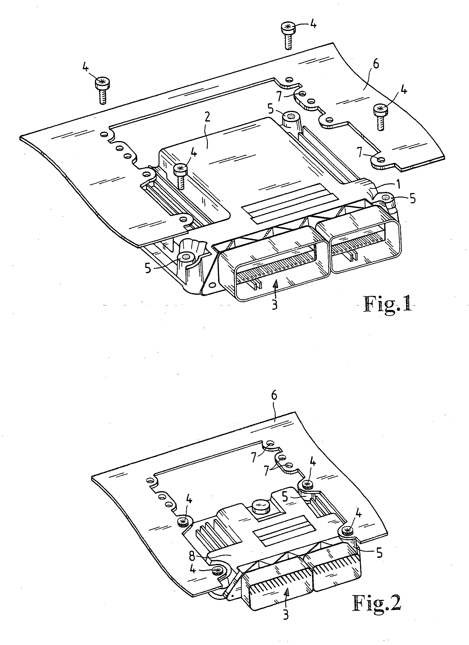
[0012] FIG. 1 is an exploded view of an arrangement having a control unit 1, of which here only the housing 2 and a multipoint connector 3, for electrically connecting electrical terminals of the control unit 1 to the electromechanical or other electronic assemblies, not shown here, that are to be controlled in a motor vehicle, are visible.

[0013] The housing 2, or a diecast cap of the housing 2, has screw domes 5, which can be drilled, cut or cast, for receiving self-tapping or standardized metric screws 4 as mounting elements.

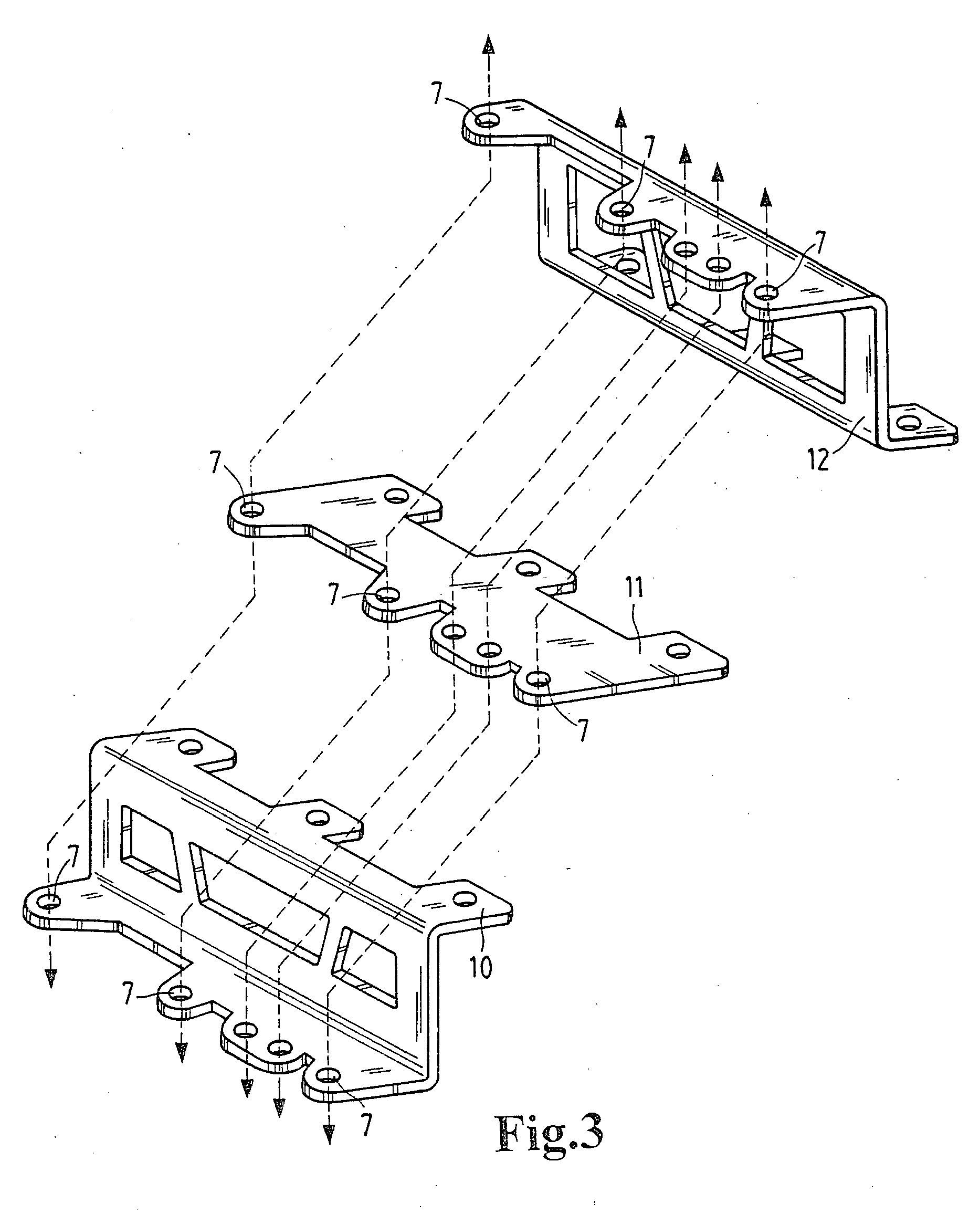
[0014] For mounting the housing 2, a supporting part 6, which either is part of a sheet-metal motor vehicle body part or is an angle bracket, has a predetermined arrangement of receiving holes through which the screws 4 can be passed for securing the housing 2 to the supporting part 6. Because of the screw points 5 on the housing and the holes 7 on the supporting part 6, which are all always located at the same point, a mechanical standard interface is formed,...


PUM


Abstract

The invention relates to a mounting device for an electrical unit (1), having at least one mounting element (4), which is anchored to the part (6; 10; 11; 12) that supports the electrical unit (1) and in the housing (2) of the electrical unit (1). A matching geometric distribution of the devices (5, 7) for receiving the mounting elements (4) is made on the housing (2) and on the part (6; 10; 11; 12) supporting the housing (2), in such a way that the devices (5) on the housing (2), in the installation position, each face some of the devices (7) on the supporting part (6). The devices on the housing (2) are preferably screw-in domes (5), into which self-tapping screws (4), as mounting elements, can be screwed.

Description

PRIOR ART[0001] The invention relates to a mounting device for an electrical unit, in particular an electrical control or regulating unit for an electromechanical assembly, as generically defined by the preamble to the main claim.[0002] In mounting such housings for an electrical unit, such as a control unit in a motor vehicle, quite various housing designs, with the most various interface definitions, must often be mounted at certain points in the motor vehicle. For that purpose, suitable angle brackets are typically secured to the electrical unit via the clamping mechanism of the printed circuit board on the one hand and on the other to the supporting parts in the motor vehicle, such as assemblies or sheet-metal parts of the auto body, which can lead to a high vibration load in operation.ADVANTAGES OF THE INVENTION[0003] A mounting device for an electrical unit, having at least one mounting element which is anchored to the part that supports the electrical unit and in the housing ...

Claims


Application Information

Patent Timeline
IPC IPC(8): B60R16/02B60R11/02H05K5/00H05K5/02
CPCH05K5/0073H05K5/0204
Inventor MAYER, FRANKSCHIEFER, PETER
Owner ROBERT BOSCH GMBH
Why Eureka
Try Eureka