
Electrohydrodynamic microfluidic mixer using transverse electric field

a microfluidic mixer and electrohydrodynamic technology, applied in the direction of fluid pressure measurement, liquid/fluent solid measurement, peptide measurement, etc., can solve the problem of prohibitively long channels, difficult to achieve diffusive mixing in microchannels, and difficult to achieve mixing in microchannels. problem, to achieve the effect of reducing the cost of manufacturing, the approach is complicated and the effect of increasing the complexity of the microfluidic mixer

Inactive Publication Date: 2004-11-25
NEW JERSEY INSTITUTE OF TECHNOLOGY
View PDF6 Cites 22 Cited by
  • Summary
  • Abstract
  • Description
  • Claims
  • Application Information

AI Technical Summary

Problems solved by technology

But mixing in microchannels is typically difficult to achieve because of the miniature scale involved.
Diffusive mixing has been found to be a relatively slow process that relies on a prohibitively long channel to accomplish the mixing.
Of these devices, certain active devices involve moving parts that are not amenable to replication at the miniature scale on the order of microns.
This approach presents added complexity for the fabrication of such microfluidic mixers.

Method used


Image

  • Electrohydrodynamic microfluidic mixer using transverse electric field
  • Electrohydrodynamic microfluidic mixer using transverse electric field
  • Electrohydrodynamic microfluidic mixer using transverse electric field

Examples


Embodiment Construction

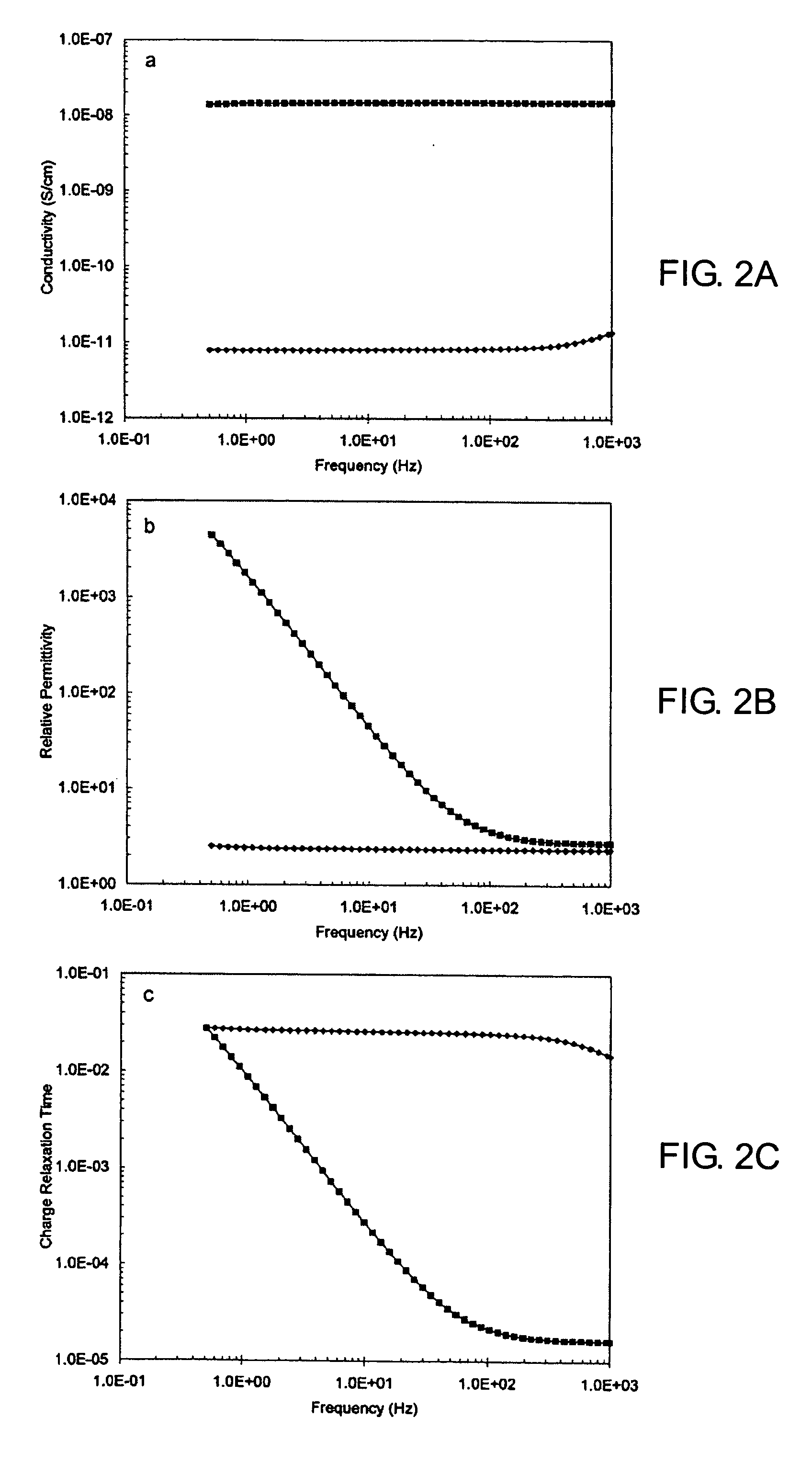
[0024] In the following description, we will explain details about an active microfluidic mixer based on both an electric force generated in presence of an applied transverse electric field and nonuniformities in predetermined electrical properties of the fluids. In particular, two fluids with identical mechanical properties and different conductivity and permittivity are used in the mixer. In the absence of an electric field, mixing is very poor and the two fluids meet only in the mid-plane at a flat interface. When the electrodes are energized by the applied field, the field creates a strong force substantially perpendicular (normal) to the interface causing the two fluids to intermingle and therefore enhancing mixing between the two fluids. In the embodiments described herein where the fluids flowed at a volume flow rate of 0.26 ml / s (corresponding to a Reynolds number less than 0.02) in a microchannel of cross-section 250 .mu.m.times.250 .mu.m, the fluids were mixed quasi-instan...


PUM

PropertyMeasurementUnit
widthaaaaaaaaaa
volume flow rateaaaaaaaaaa
thickaaaaaaaaaa

Abstract

Simplicity of design is achieved for an electrohydrodynamic microfluidic mixer by applying an electric field substantially transverse to the flow direction and substantially orthogonal or normal to the interfacial plane between the fluids being mixed in the main channel. The electric field is wide enough to encompass substantially the entire depth of the main channel in the microfluidic mixer. In one exemplary embodiment, the electrohydrodynamic microfluidic mixer comprises a substrate, one main channel disposed on the substrate, first and second inlet channels disposed on the substrate and individually coupled to the main channel, and first and second electrodes disposed on opposite sides of the main channel for applying an electric field across the main channel substantially transverse to the flow direction in the main channel. Field uniformity across the desired cross-section of the main channel is achieved by having the electrode thickness be substantially equal to the main channel depth. Disposition of the electrodes is judiciously controlled to generate the electric field in a direction substantially orthogonal or normal to the interfacial plane between the fluids in the main channel.

Description

CROSS-REFERENCE TO RELATED APPLICATIONS[0001] This application claims benefit of U.S. provisional patent application Ser. No. 60 / 472,573, filed May 22, 2003, which is herein incorporated by reference in its entirety.BACKGROUND OF THE INVENTION[0002] 1. Field of the Invention[0003] This invention relates to the field of microchannel devices and, more particularly, to such active devices that perform microfluidic mixing of two or more fluids flowing in the microchannel by using an applied electric field.[0004] 2. Description of the Related Art[0005] Fluid mixing in microchannels is needed for many applications ranging from miniaturized analytical and synthetic chemistry to DNA microarray technology to the transport of small quantities of dangerous or expensive materials. But mixing in microchannels is typically difficult to achieve because of the miniature scale involved.[0006] Fluid flows in micron-scale straight channels having smooth walls are laminar and uniaxial and occur at low ...

Claims


Application Information

Patent Timeline
Patent Type & Authority Applications(United States)
IPC IPC(8): B01FB01F13/00H01L29/76H01L31/062
CPCB01F13/0076B01F33/3031
Inventor AUBRY, NADINE NINABATTON, JOHN LYLEEL MOCTAR, AHMED OULD
Owner NEW JERSEY INSTITUTE OF TECHNOLOGY
Learn More