Micro force gages and calibration weights

a micro force gage and calibration weight technology, applied in the field of micro force gages and calibration weights, can solve the problems of high margin of error, and achieve the effect of optimizing the reliability of calibration, directly and conveniently measuring

Inactive Publication Date: 2004-07-22
KELLER CHRISTOPHER GUILD
View PDF8 Cites 4 Cited by
  • Summary
  • Abstract
  • Description
  • Claims
  • Application Information

AI Technical Summary

Problems solved by technology

The margin of error is high.

Method used


Image

  • Micro force gages and calibration weights
  • Micro force gages and calibration weights
  • Micro force gages and calibration weights

Examples


Embodiment Construction

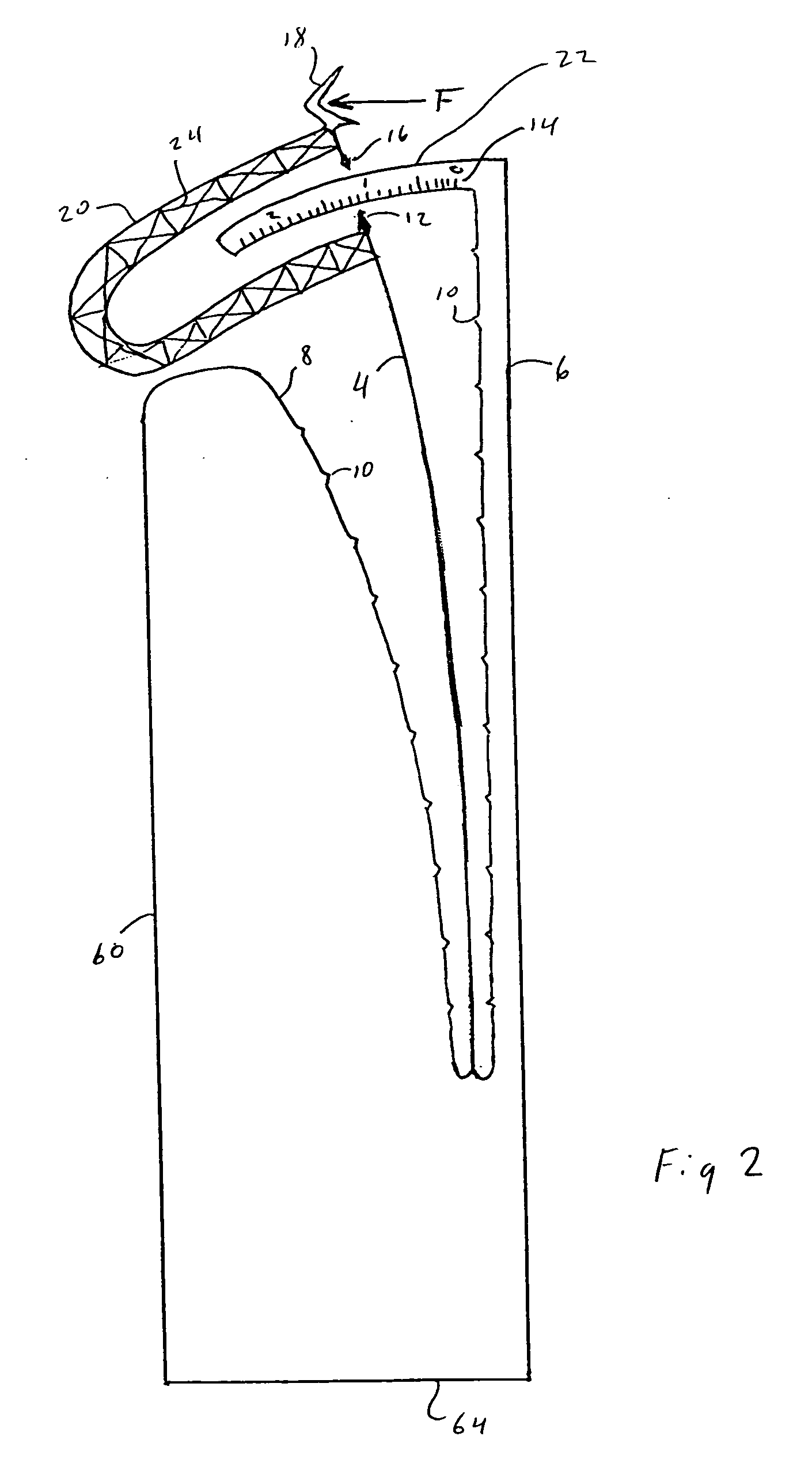
[0056] FIG. 1 shows one embodiment of the force gage (2). The force sensitive part is the elastic cantilever (4). When a force is pushing or pulling on the tip (18) of the gage, the cantilever (4) will deflect by an amount proportional to the magnitude of the force. The amount of deflection can be read on the graduated scale (14) using either pointer (12) or (16). A rigid connecting arm (20) goes around the graduated scale support structure (22) to rigidly connect tip (18) to the end of the cantilever. To make the connecting beam 20 rigid but as light weight as possible, it is not solid but is comprised of an open trusswork of thin beams (24). The cantilever (4) is protected from being hit by objects to by rigid bar 3 and the other rigid protective side (60). The curved edge (8) is designed to match the curve of the deflected cantilever at the maximum allowed deflection. The anti-stiction bumps (10) minimize the contact area confronting the cantilever if a liquid is present to cause...


PUM

PropertyMeasurementUnit
forces of magnitudeaaaaaaaaaa
heightaaaaaaaaaa
lengthaaaaaaaaaa

Abstract

The invention is a microfabricated silicon cantilever with a stiffness appropriate to resolve forces of interest in working with micro objects. Stiffnesses may range from about 10 piconewtons per micron of deflection, to about 1 millinewton per micron of deflection. There is a set of micro weights of appropriate masses that is used to calibrate the force gages. The weights are captive to a ring on a handle so that they are free to move, but will not get lost.

Description

[0001] This patent application claims the benefit of Provisional Patent Application No. 60 / 439,915 filed on Jan. 13, 2003.[0002] 1. Field of Invention[0003] The field of invention is devices for the measurement of forces of magnitude ranging from about 1 piconewton to about 10 millinewtons, and the dead weights needed to calibrate them.[0004] 2. Discussion of Prior Art[0005] Precision force gauges on the macroscale are calibrated with dead weights that are traceable to standard precision weights by the National Institute of Standards and Technology. Prior art microscale force gauges are calibrated indirectly by measuring their resonance frequencies, and calculating their stiffness. The margin of error is high. Microfabricated cantilevers of the prior art for measuring forces are all made with the bending axis parallel to the plane of the silicon wafer. This restricts the geometry of the tip that engages the specimen to a simple column or pyramid shape.OBJECTS AND ADVANTAGES[0006] Th...

Claims


Application Information

Patent Timeline
Patent Type & Authority Applications(United States)
IPC IPC(8): G01L1/04
CPCG01L1/044
Inventor KELLER, CHRISTOPHER GUILD
Owner KELLER CHRISTOPHER GUILD
Why Eureka
Try Eureka