Light amount adjusting device, and optical device using the light amount adjusting device
a technology of light amount and adjustment device, which is applied in the direction of optical elements, instruments, television systems, etc., can solve the problems of deterioration of optical performance due to light diffraction, deterioration of optical performance, and inability to take concrete measures
- Summary
- Abstract
- Description
- Claims
- Application Information
AI Technical Summary
Problems solved by technology
Method used
Image
Examples
first embodiment
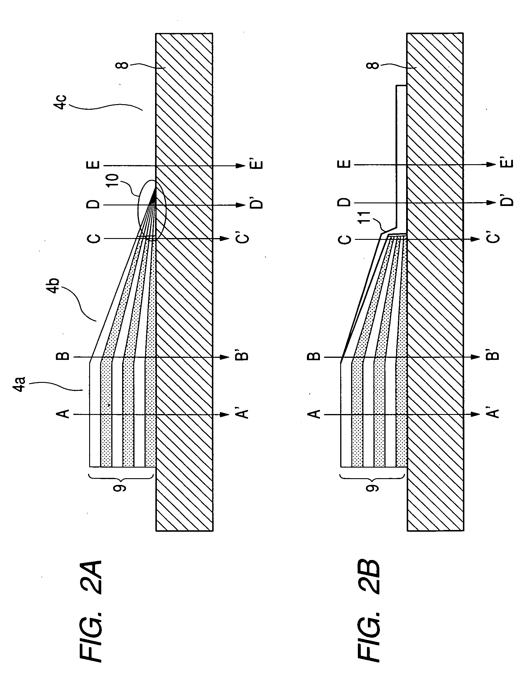
[0054] FIG. 2A is the sectional view showing the gradation ND filter according to a Although the description is repeated, as shown in FIG. 2A, the ND evaporation film 9 is formed on the surface of the filter base 8 which serves as a filter member, has a film-like shape, and is made of a resin. The ND filter includes: the low transmittance region 4a which is a region in which the thickness of the ND evaporation film 9 is kept constant; the gradation ND region 4b in which the thickness of the ND evaporation film 9 successively changes (section B-B' to section C-C'); and the transparent region 4c in which the ND evaporation film 9 is not formed.
[0055] In FIG. 2A, the ND density of the low transmittance region 4a in which the thickness of the ND evaporation film 9 is largest among these regions becomes 1.3. In the gradation ND region 4b, the ND density is successively changed in a range of 1.2 to 0.1 due to the presence of the sloped evaporation film.
[0056] In the gradation ND region, ...
second embodiment
[0095] Next, FIG. 12 shows a relationship between an MTF value and T No. in a light amount diaphragm including the gradation ND filter according the
[0096] The ND densities of the gradation ND region are set to ND 1.5 to ND 0.5. This is the case where the ND density difference in the boundary between the transparent portion and the gradation ND region is ND 0.5. The transmission wave front phase difference in the boundary portion is .lambda. / 5.
[0097] From the F3.3 state (C) to the F5 state (D), the MTF value reduces to 22%. A main factor of the deterioration of the optical performance is because the transmission wave front phase difference of .lambda. / 5 is produced in the boundary between the transparent portion and the gradation ND region. As is apparent from this embodiment, even if the gradation ND region is used, in the case where the transmission wave front phase difference in the boundary portion is .lambda. / 5 or more, there is no effect to the improvement of the optical perfor...
third embodiment
[0098] Next, FIG. 13 shows a relationship between an MTF value and T No. in a light amount diaphragm including the gradation ND filter according the
[0099] The ND densities of the gradation ND region are set to ND 1.7 to ND 0.2.
[0100] From the fully-opened state (A) to the F5 state (D), the MTF value of 42% or more is maintained and this is preferable. Because the ND density of a dense portion is ND 1.7 (transmittance is 2%), even in the T No. 22 state at the imaging of a high brightness object, the MTF value of 45% can be maintained in the case where the diaphragm aperture is in the F6.8 state. However, in the case where the ND density becomes higher than 1.7, the transparent portion and an ND 1.7 portion are present in the diaphragm aperture in an intermediate diaphragm state. Therefore, a difference in a light amount is produced between the upper side and the lower side of an imaging screen, so that a problem with respect to unevenness in light amount which is called shading is ca...
PUM
 Abstract
Description
Claims
Application Information
 - R&D
- Intellectual Property
- Life Sciences
- Materials
- Tech Scout
- Unparalleled Data Quality
- Higher Quality Content
- 60% Fewer Hallucinations
Browse by: Latest US Patents, China's latest patents, Technical Efficacy Thesaurus, Application Domain, Technology Topic, Popular Technical Reports.
© 2025 PatSnap. All rights reserved.Legal|Privacy policy|Modern Slavery Act Transparency Statement|Sitemap|About US| Contact US: help@patsnap.com


