
Apparatus for detecting or predicting tool breakage

a technology for predicting and detecting tools, applied in the direction of instruments, program control, nuclear elements, etc., can solve the problems of deteriorating machining accuracy, inability to maintain predetermined machining accuracy required of workpieces, and wear of cutting edges of tools used in machine tools

Inactive Publication Date: 2004-04-08
FANUC LTD
View PDF4 Cites 44 Cited by
  • Summary
  • Abstract
  • Description
  • Claims
  • Application Information

AI Technical Summary

Problems solved by technology

In general, a cutting edge of a tool used in a machine tool wears and cutting resistance increases with a passage of time in which the tool is used for machining.
As the wear advances, machining accuracy deteriorates and predetermined machining accuracy required of a workpiece cannot be maintained.
Recent cutting is fast, a rotational speed and a feed speed of the tool are high, and a cycle time is short.
Therefore, reference waveform data stored as reference values gets a high density and requires a large storage capacity and it is difficult to perform real-time comparison processing when the tool is in abnormal condition.
Therefore, it is difficult in practice to uniformly set proper thresholds for judging tool breakage torque and / or thrust load in advance.
This operation is extremely complicated.
Therefore, if the tool breakage torque and / or thrust value(s) to be set as a threshold which is a criterion for detecting / predicting the tool breakage is set at the start, the breakage cannot be predicted or the tool may be judged to be in abnormal condition when it is not in some cases.
In this case, if a threshold for detecting abnormal condition is obtained based on an average value of loads in one machining cycle, it is difficult to detect an abnormal condition and the like of the tool.

Method used


Image

  • Apparatus for detecting or predicting tool breakage
  • Apparatus for detecting or predicting tool breakage
  • Apparatus for detecting or predicting tool breakage

Examples


Embodiment Construction

[0031] FIGS. 5 to 8 show measurement values of a load (thrust load) in a direction of a tool feed shaft (Z axis) in a machining cycle in which a drill of a tool got broken and a plurality of machining cycles before the cycle, in case where drilling by using the drill was carried out. In these drawings, a reference horizontal axis indicates a position where a machining load at the time when a main shaft is idling is zero and a black dot indicates a position where load data is obtained. In this example, measurement data are obtained at intervals of 8 milliseconds. In the following description, a cutting time of drilling is referred to as a value T, an area (an integrated value of a load value) of a cutting load waveform during cutting is referred to as a value S, and a maximum value (an absolute value) of a slope of a drop in the cutting load is referred to as a value G. The value G is obtained from a difference between measured loads at measurement intervals of 8 milliseconds during ...


PUM


Abstract

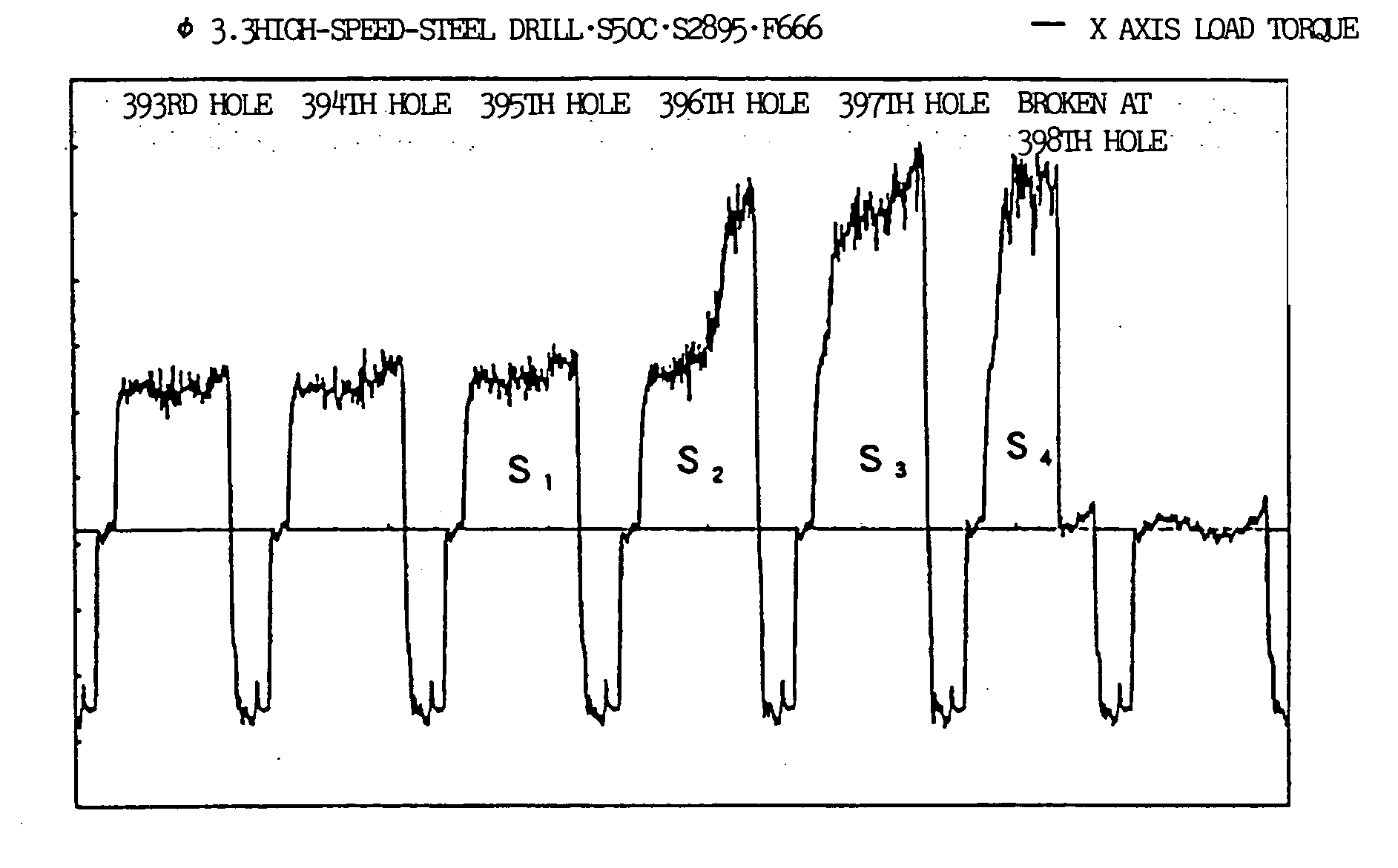
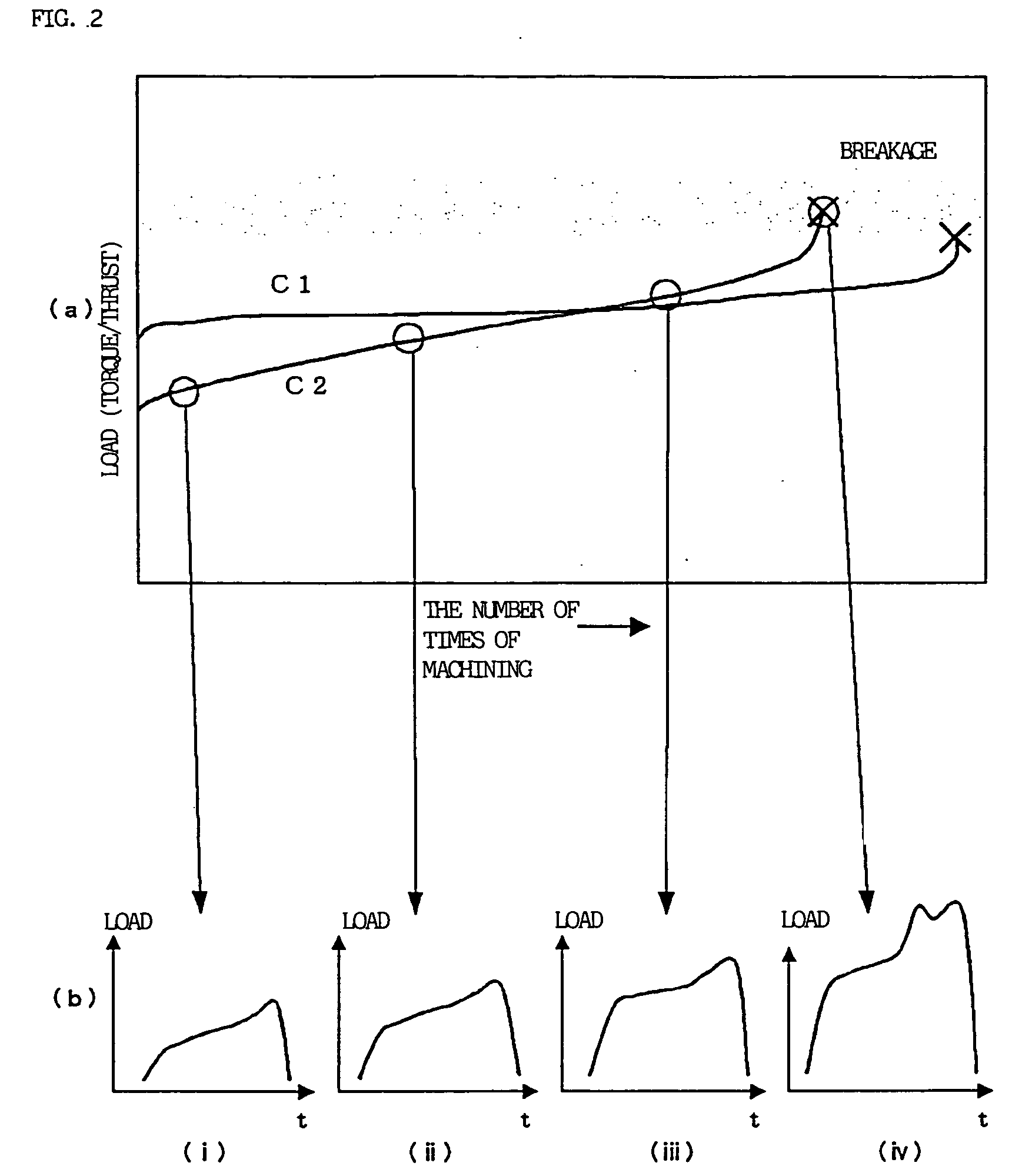
If a tool breakage occurs, a cutting time T and a maximum value (absolute value) G of a slope of a drop in a cutting load become small. A cutting load integrated value S increases as a tool wears and becomes small when the breakage occurs. Therefore, these values T, G, and S are obtained in a machining cycle, moving variable thresholds are obtained (updated) based on values T, G, and S obtained in a preceding machining cycle, and the thresholds and the values T, G, and S obtained in the current machining cycle are compared with each other to thereby determine an abnormal condition of the tool.

Description

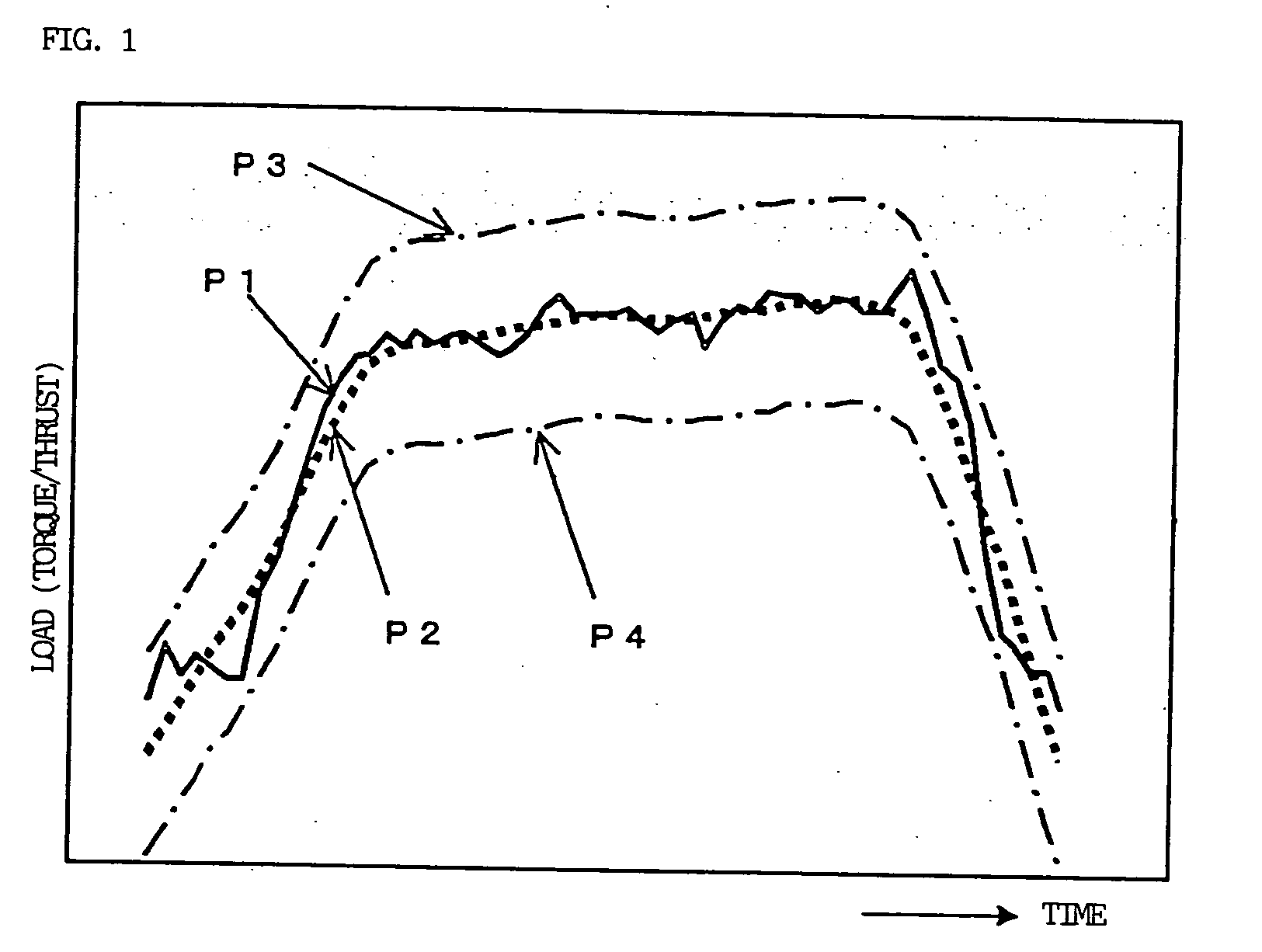
[0001] 1. Field of the Invention[0002] The present invention relates to detection or prediction of a breakage of a tool used for machining workpieces made of the same material into the same shapes or for continuously machining the large number of workpieces such as parts of the same specifications.[0003] 2. Description of the Related Art[0004] In general, a cutting edge of a tool used in a machine tool wears and cutting resistance increases with a passage of time in which the tool is used for machining. As the wear advances, machining accuracy deteriorates and predetermined machining accuracy required of a workpiece cannot be maintained. Then, the tool reaches an end of its life.[0005] By the way, as an apparatus for detecting abnormal condition of a tool which reaches an end of its life due to automatic machining for many hours, it is proposed that an upper-limit permissible value P3 and a lower-limit permissible value P4 are obtained for a reference waveform P2 and that a deviatio...

Claims


Application Information

Patent Timeline
Patent Type & Authority Applications(United States)
IPC IPC(8): B23B49/00B23Q11/04B23Q17/09G05B19/4065
CPCB23Q11/04G05B19/4065G05B2219/37229B23Q17/0961G05B2219/37285B23Q17/0957G05B2219/37245
Inventor MAEKAWA, SUSUMUYASUGI, KUNIHARU
Owner FANUC LTD
Learn More