Discsmark tm marker, a marker to locate and identify objects above and below ground

a technology of object identification and marker, which is applied in the direction of boundary marks, traffic signals, ways, etc., can solve the problems of time-consuming, time-consuming, and expensive, and the thin wall body marker can easily be vandalized, and cannot withstand vehicular traffic as well as a solid body marker

Inactive Publication Date: 2004-02-19
FONG BUDDY +1
View PDF0 Cites 20 Cited by
  • Summary
  • Abstract
  • Description
  • Claims
  • Application Information

AI Technical Summary

Problems solved by technology

However, whenever a new house is constructed, even when there are markers that are present to identify the property, a new survey is required because the markers are not identified.
Both of these are easy to put on and easily taken off and both require that information, supplied by surveyors and engraved by a supplier (which is time delaying, time consuming, and expensive); and which, contributes to why surveyors do not permanently identify their markers.
A thin wall body marker can easily vandalized with a knife or box cutter and cannot withstand vehicular traffic as well as a solid body marker.
The marker claimed to have an opening to accommodate the rectangular stake, which means that if the stake is not properly oriented before driving the stake, the marker having directional indicia integrally formed thereon cannot be rotated to adjust for error if made when driving the stake.
This invention may not be on the market and would be costly, and certainly could not be used in asphalt.
Even if markers are found, one cannot be certain what they represent if they are not marked to identify themselves.
This leads to expensive survey service and time delays.
Existing found markers or pins, if not identified, may not be a reliable source to set property lines by.
In construction, these costs become more expensive if connections to existing utilities are required.

Method used


Image

  • Discsmark tm marker, a marker to locate and identify objects above and below ground
  • Discsmark tm marker, a marker to locate and identify objects above and below ground
  • Discsmark tm marker, a marker to locate and identify objects above and below ground

Examples


Embodiment Construction

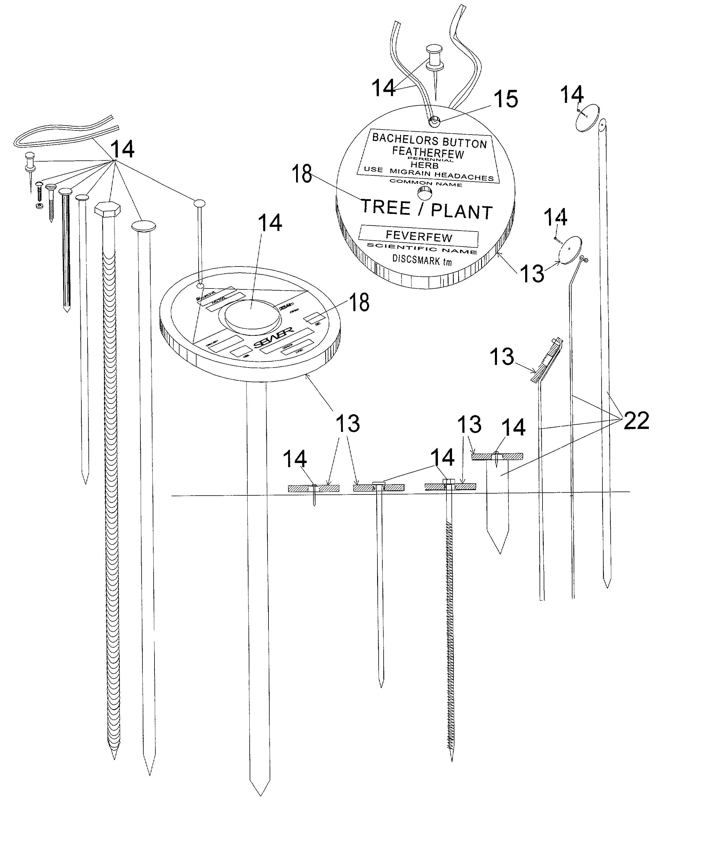
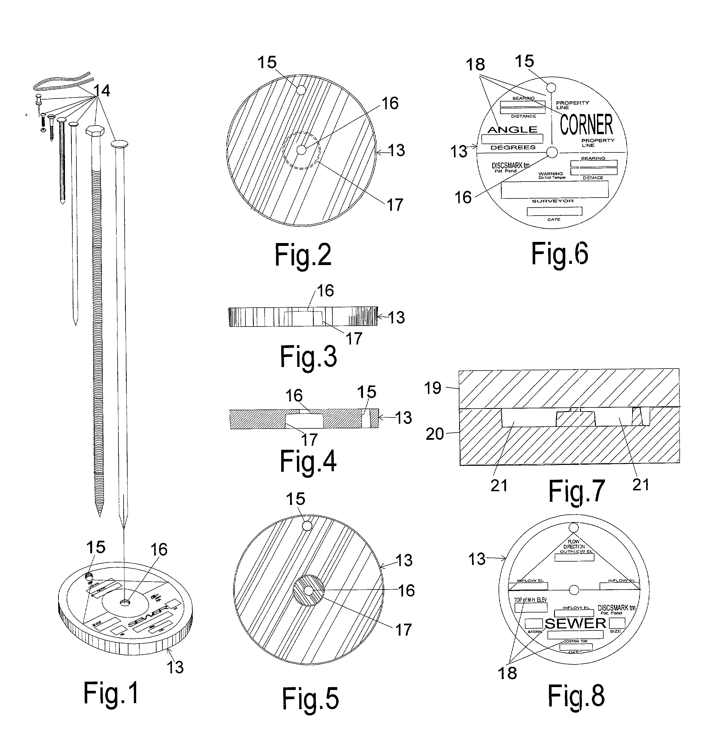
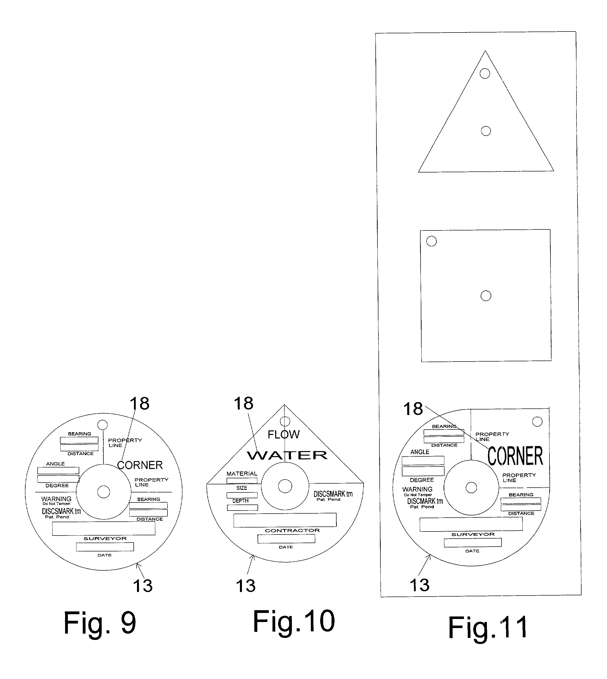
[0051] A preferred embodiment of the marker 13 of this present invention is illustrated in FIG. 1 (perspective), FIG. 2 (top view) with no information imprinted thereon, FIG. 3 (side view) by FIG. 4 (cross section) and FIG. 5 (bottom view) and FIG. 6 (top view) showing a variation of information permanently imprinted thereon. The preferred shape is a round flat disc 13 with a solid body with a varying size round hole through the center of the body to accommodate varying types and sizes of anchors to be provided by the user. A hole 16 at the center and top of the marker shall be approximately 1 / 8 inch in diameter and the connecting hole 17 at the bottom of the marker shall be approximately 1 / 2 inch in diameter. The center of these holes shall be aligned to center on each other. Another hole 15 can be used for attachment or stabilization.The flat embodiment provides for visibility and for an areas for information to be permanently imprinted on the top of the marker and to provide area...


PUM


Abstract

A marker in the shape of a flat round disc that has varying permanent information (18) (for identifying different objects) imprinted upon the top of the marker that identifies the marker's use and areas for information to be permanently inscribed by a user with a portable electric en-graving tool or for temporary information to be placed thereon. The marker has a varying size holes(16), (17) through the center of the marker from top to bottom that allows different types and sizes of anchors to be used to attach the marker to varying surfaces or mounting devices or materials. The marker has an additional hole (15) for other means of attachment. The marker is solid and made of a plastic that will flex and give and is permanent and durable and is produced in varying colors for visibility and identifying different objects.

Description

[0001] Not Applicable.[0002] 1. Field of Invention[0003] This invention relates to markers use to locate objects above and below ground, permanently or temporally.[0004] 2. Description of Prior Art[0005] There are objects above and below ground that could be marked to show their location and provide information of interest about such objects and the items they contain, as well as information about the marker itself.[0006] Some objects, if located and marked when installed, would save money by not having to be located at a later date.[0007] Other items could be marked to provide information for knowledge and convenience of identity.[0008] Such objects would include property line; corners, transitions points, and benchmarks; underground utilities such as; water, sewer, electricity, gas, water drainage, telephone, and cable, storage tanks, septic tanks and field lines, trees, plants, and planted garden and plant seeds.[0009] Most states require that surveyors identify property corners ...

Claims


Application Information

Patent Timeline
IPC IPC(8): G01C15/04
CPCG01C15/04
Inventor FONG, BUDDYFONG, GERALD WAYNE
Owner FONG BUDDY
Why Eureka
Try Eureka