Application device

a technology of application device and cross-direction profile, which is applied in the field of application device, can solve the problems of corresponding interruption, uneven cross-direction profile, and markings in the area of reversal points

Inactive Publication Date: 2004-01-22
VOITH PATENT GMBH
View PDF2 Cites 8 Cited by
  • Summary
  • Abstract
  • Description
  • Claims
  • Application Information

AI Technical Summary

Benefits of technology

[0017] It is also advantageous if the direction of movement can be reversed after a complete rotation.

Problems solved by technology

If the functioning of one or several nozzles is interrupted, it necessarily also results in a corresponding interruption of the moistening profile formed transverse to the machine in the area of the effective width of a respectively interrupted nozzle.
The resulting cross direction profile thus becomes uneven.
Moreover, the oscillating spraying pipes have the disadvantage that markings can occur in the area of the reversal points.

Method used


Image

  • Application device
  • Application device

Examples


Embodiment Construction

[0031] The particulars shown herein are by way of example and for purposes of illustrative discussion of the embodiments of the present invention only and are presented in the cause of providing what is believed to be the most useful and readily understood description of the principles and conceptual aspects of the present invention. In this regard, no attempt is made to show structural details of the present invention in more detail than is necessary for the fundamental understanding of the present invention, the description taken with the drawings making apparent to those skilled in the art how the several forms of the present invention may be embodied in practice.

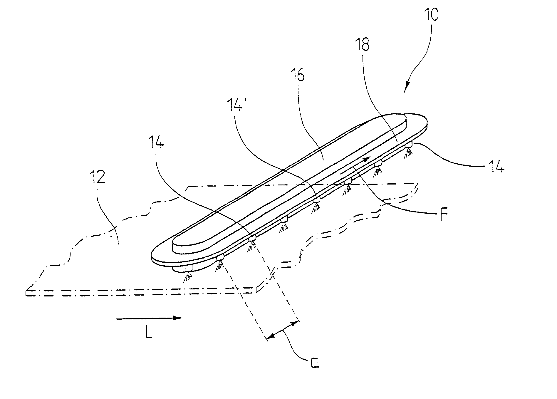
[0032] FIG. 1 shows, in a purely schematic representation, an exemplary embodiment of an application device that in the present case is formed for example by a conditioning device 10. It can among other things take on e.g. the function of a spray- or cleaning spraying pipe or a nozzle moistener. In principle, however, an...


PUM


Abstract

Application device for impinging on an element of a machine, including a plurality of nozzle units arranged at a respective distance from one another, the nozzle units being conveyed in a closed rotating path in a first direction extending generally transversely to a machine travel direction.

Description

[0001] The present application claims priority under 35 U.S.C. .sctn. 119 of German Patent Application No. 101 15 726.6, filed on Mar. 30, 2001, the disclosure of which is expressly incorporated by reference herein in its entirety.[0002] 1. Field of the Invention[0003] The invention relates to an application device, in particular for a paper machine, having a plurality of nozzle units arranged at a respective distance from one another. Such application devices are known, for example, from DE-C-39 29 561, EP-A-0 960 656, and DE-A-199 21 592.[0004] 2. Discussion of Background Information[0005] Up to now machine-wide spraying pipes have been used in paper machines in order e.g. to moisten or clean the covering, dewatering elements, rolls, or machine elements with a fluid. These spraying pipes are either stationary or are provided such that they can execute a positioning lift that can be a multiple of the distance between two adjacent nozzles. If the functioning of one or several nozzle...

Claims


Application Information

Patent Timeline
Patent Type & Authority Applications(United States)
IPC IPC(8): D21F1/32D21G7/00
CPCD21G7/00D21F1/32
Inventor GRABSCHEID, JOACHIMBEGEMANN, ULRICHSATZGER, OSWALDMAYER, WOLFGANGRZIHA, RALFBAMBERGER, WOLFGANGKLEISER, GEORGRUHL, THOMAS
Owner VOITH PATENT GMBH
Why Eureka
Try Eureka