
Multi-lens hydrogen, electric and steam power plant

Inactive Publication Date: 2004-01-22
SUNIN
View PDF3 Cites 7 Cited by
  • Summary
  • Abstract
  • Description
  • Claims
  • Application Information

AI Technical Summary

Problems solved by technology

This type of power plant is capable of collecting a relatively large quantity of heat but cannot raise the temperature enough, and the structure is rather high and expensive.

Method used


Image

  • Multi-lens hydrogen, electric and steam power plant
  • Multi-lens hydrogen, electric and steam power plant
  • Multi-lens hydrogen, electric and steam power plant

Examples


Embodiment Construction

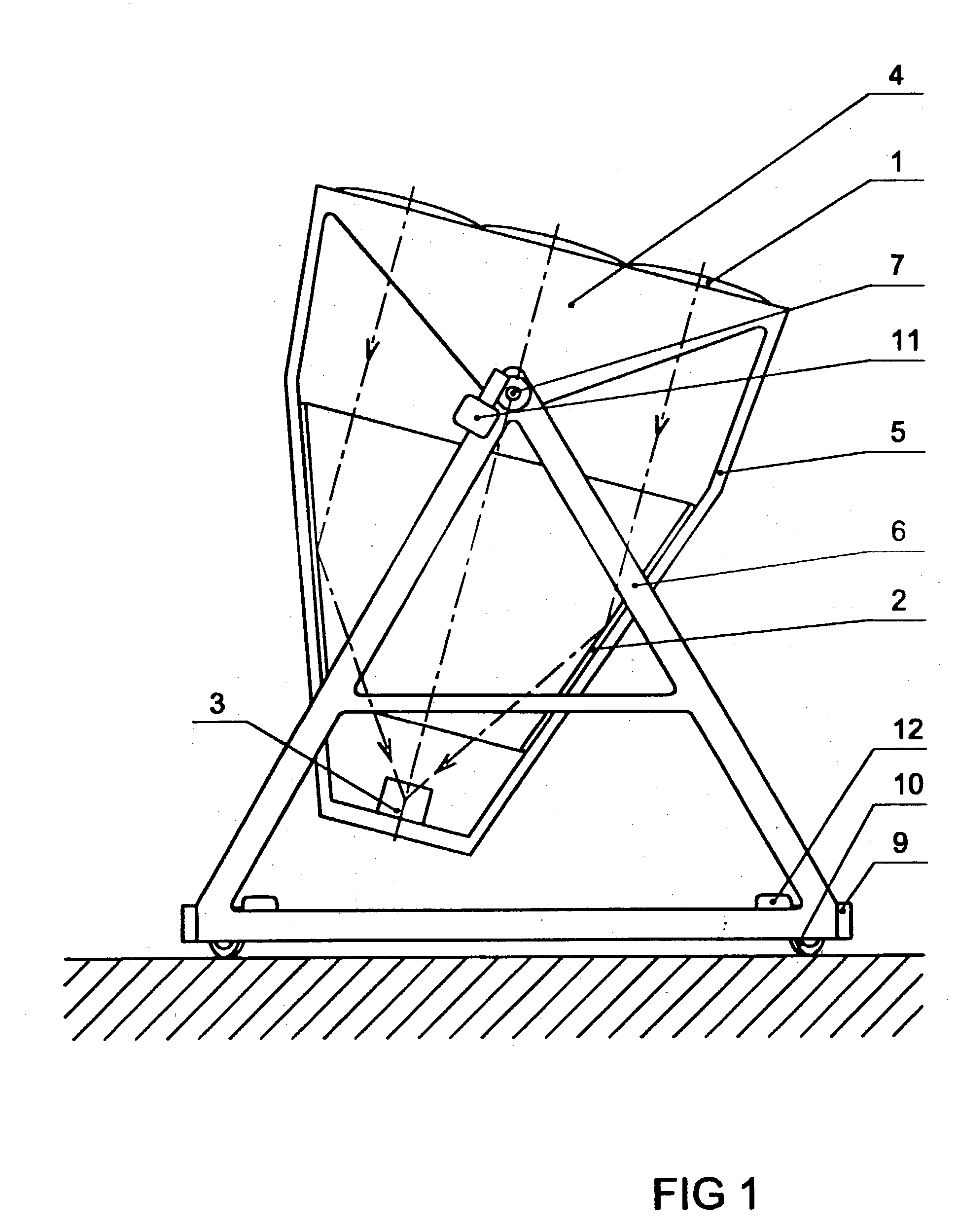
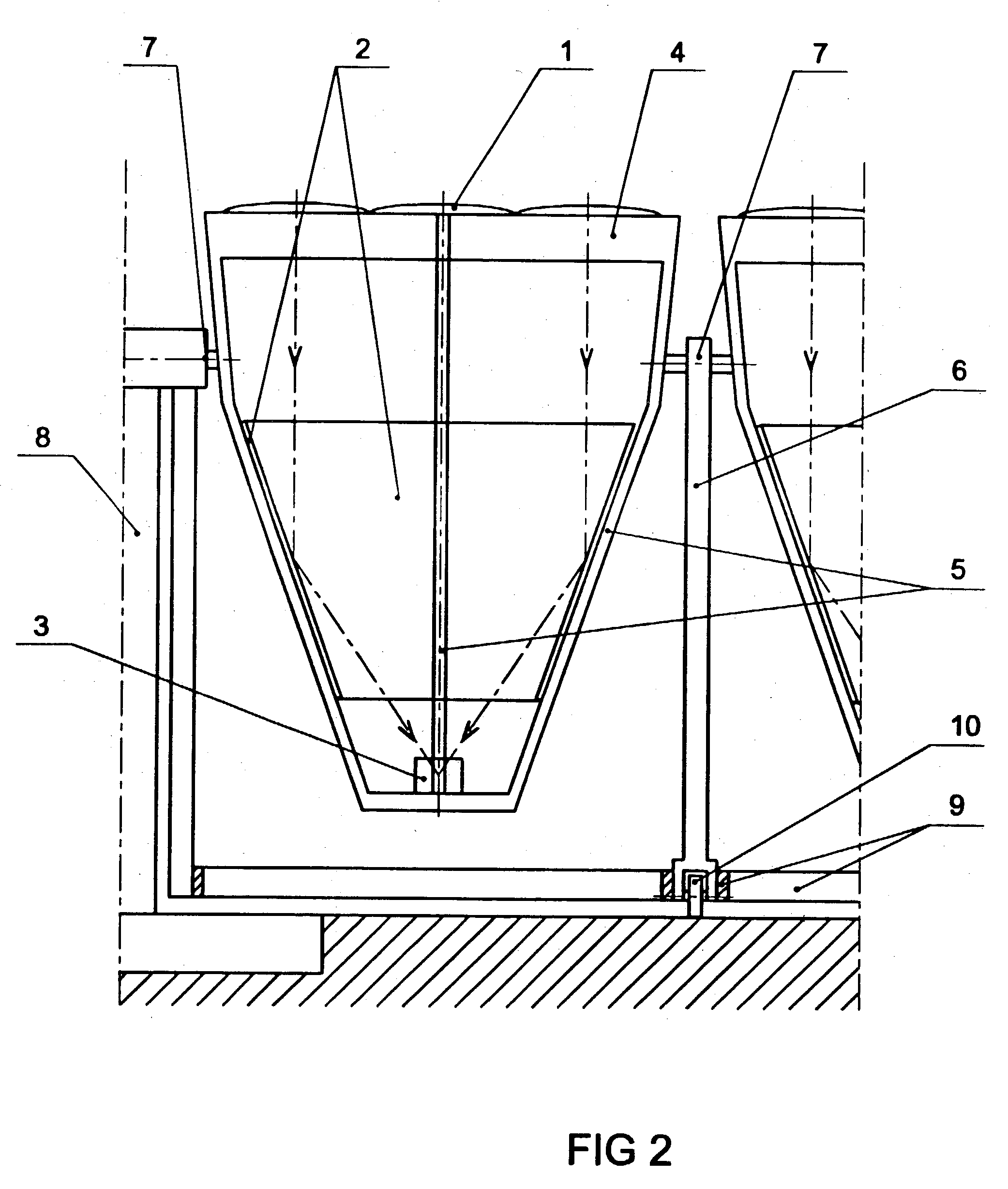
[0019] In a hydrogen power plant there are pillow lenses 1, diameter 1.8 meters. In a frame 4 there is a group of nine lenses. In the focal point there is an apparatus 3 where a ceramic water splitter is placed. In an electric / steam power plant there are, accordingly, 0.6-meter lenses, and the focal point apparatus 3 is provided with a vaporiser. Flat mirrors 2 reflect ray bundles from eight lenses into the apparatus 3 placed in the focal point of the ninth lens, which is in the middle of the group.

[0020] In a hydrogen power plant there are 2.times.12 frames and in an electric / steam power plant 6.times.36 frames side by side. The lens surfaces have a height of 10.8 meters, a length of 64.8 meters and an area of about 700 square. The effective output is about 400 kW.

[0021] In the middle of each frame 4 there is a column 8 provided with a bearing housing. The frames are mounted onto the columns and bases 6 by means of bearings 7. In vertical direction, the frames 4 are turned towards ...


PUM


Abstract

In a multi-lens hydrogen and / or electric / steam power plant there are mirrors 2, or equivalent, such as prisms, placed underneath lenses 1 directing ray bundles from several lenses 1 onto one focal point. There are for instance nine lenses 1 in a frame 4, and underneath the outermost lenses 1 there are diagonally placed flat mirrors 2 directing ray bundles to a water splitter or a vaporizer placed in an apparatus 3 in the focal point. There may be for instance ten frames 4 side by side, and in the middle there may be a supporting column 8 provided with bearings 7; and between the frames 4 there may be bases 6 with wheels 10 underneath. Directing the frame in vertical direction and so as to follow the Sun's rotation there may be motors 11 and 12 controlled by a sensor.

Description

RELATED PATENT[0001] The present invention relates to a multi-lens hydrogen, electric and steam power plant consisting of a solar lens and a support as in European patent No. 0756690.[0002] Directing ray bundles from nine lenses on one focal point multiplies the temperature and the efficiency by about ten; and the smaller the lenses are and the shorter the focal length is enabling the production of the temperature of 4000.degree. K in the water splitter and that of about 500.degree. C. as well as a large quantity of heat in the vaporiser, the lower and lighter and sturdier and less expensive the structure of the power plant will be.[0003] To produce large quantities of hydrogen and electricity, a multi-lens solar power plant is necessary where ray bundles from several lenses heat one focal point apparatus and the frames of the lens groups and the base of the structure automatically direct themselves towards the Sun and the whole structure is strong enough to stand up to the strains ...

Claims


Application Information

Patent Timeline
IPC IPC(8): B01J19/12C01B3/04F24J2/54F24S20/20F24S23/30F24S23/79
CPCB01J19/127C01B3/042C01B2203/0805F24J2/07F24J2/08Y02E60/364F24J2/5233F24J2/542Y02E10/41Y02E10/47F24J2/18F24S20/20F24S23/30F24S23/79F24S25/13F24S30/452Y02E60/36Y02P20/133Y02E10/40
Inventor REIALA, MAUNO SAKARI
Owner SUNIN
Learn More