Adjustable and tunable hand tremor stabilizer
a hand tremor stabilizer, adjustable technology, applied in the field of medical devices, can solve the problems of inability to manage many of the routines of daily life, inability to control the hand stability and control of individuals with this problem, and device only being able to cancel out unwanted movements
- Summary
- Abstract
- Description
- Claims
- Application Information
AI Technical Summary
Benefits of technology
Problems solved by technology
Method used
Image
Examples
first embodiment
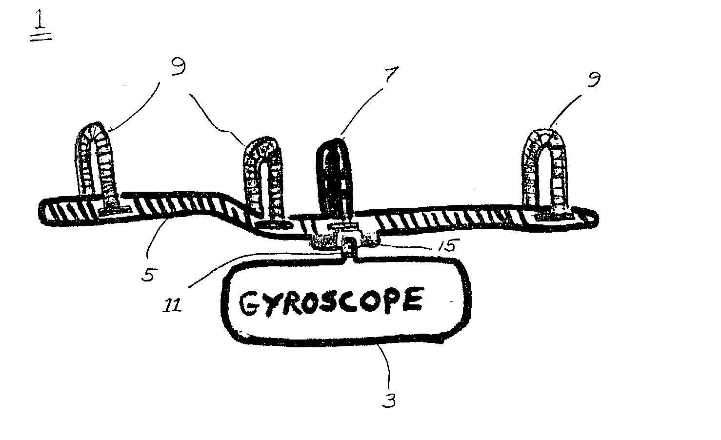
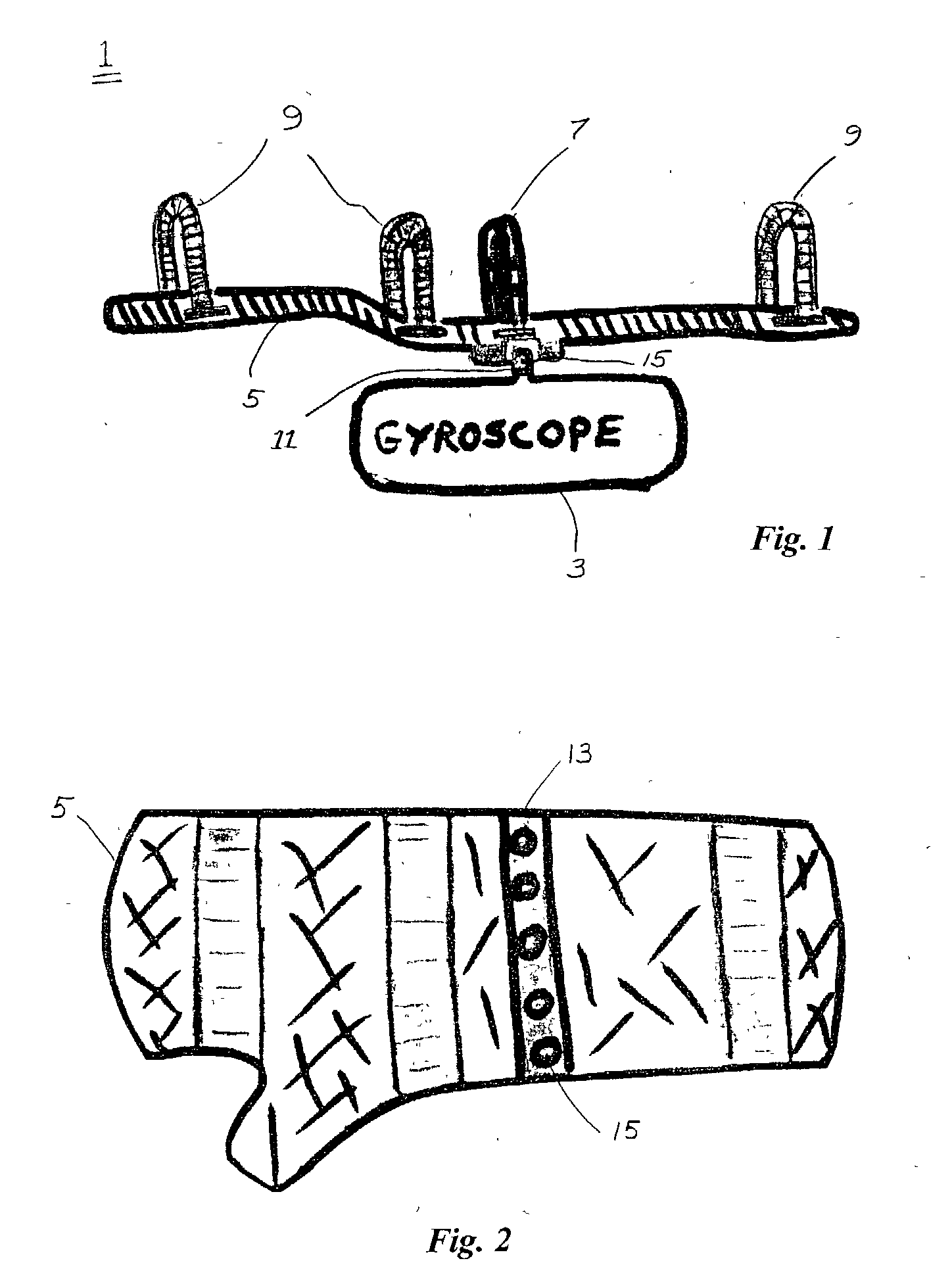
[0050] FIG. 1 illustrates a cross-sectional side view of a hand tremor stabilizer 1 with an attached gyroscope 3 which is transversely adjustable with respect to the length of the arm. A rigid splint 5 is the primary structure of the device. The splint 5 is capable of stabilizing the entire hand, wrist and forearm region of the patient. In particular, a rigid splint 5 may be utilized to join these three areas of the users body into essentially one stable and rigid structure, except for the free movement of the fingers and thumb.
[0051] The splint 5 may be made from a variety of materials already known in the art. For instance, the splint may be manufactured from sturdy, yet lightweight materials, such as aluminum, titanium, plastics or lightweight composites such as epoxy or fiberglass. Furthermore, the splint may be constructed from a variety of designs and shapes already known in the art. It should be noted that the splints disclosed in this application are merely exemplary of a ma...
second embodiment
[0054] FIG. 3 illustrates a cross-sectional side view of the hand tremor stabilizer 1 with an attached gyroscope 3 which is longitudinally adjustable. This alternative embodiment is essentially the same as the embodiment disclosed in FIG. 1 and FIG. 2, however, the transversely attached rigid mounting member 13 is replaced with a longitudinally attached rigid mounting member 17 having multiple mounting sockets or threaded holes 15.
[0055] FIG. 4 is a bottom view of the embodiment from FIG. 3, the illustrated embodiment having the longitudinally attached rigid mounting member 17 mounted to the splint.
third embodiment
[0056] FIG. 5 is a bottom view of a splint 5 with a mounting plate 19 having multiple sockets or threaded holes 15 arranged in a matrix. This embodiment provides the user with numerous choices, with respect to the attachment position of the gyroscope 3 (i.e., both transversely and longitudinally positioned).
[0057] FIG. 6 shows a side cross-sectional view of the splint illustrated in FIGS. 1 through 5.
PUM
 Abstract
Description
Claims
Application Information
 - R&D
- Intellectual Property
- Life Sciences
- Materials
- Tech Scout
- Unparalleled Data Quality
- Higher Quality Content
- 60% Fewer Hallucinations
Browse by: Latest US Patents, China's latest patents, Technical Efficacy Thesaurus, Application Domain, Technology Topic, Popular Technical Reports.
© 2025 PatSnap. All rights reserved.Legal|Privacy policy|Modern Slavery Act Transparency Statement|Sitemap|About US| Contact US: help@patsnap.com


