Above & below knee prosthesis - leg coupler

a leg coupler and prosthesis technology, applied in the field of above & below knee prosthesis leg couplers, can solve the problems of pins not aligning easily and consistently with the coupler latching mechanism, body must become integral,

Inactive Publication Date: 2003-12-18
LUND ARNOLD A
View PDF13 Cites 16 Cited by
  • Summary
  • Abstract
  • Description
  • Claims
  • Application Information

AI Technical Summary

Benefits of technology

[0079] It is seen that I have provided a unique coupler for use by prosthesis users, which is safe, positive locking and easy to use. In addition, this is the first coupler specifically designed for above the knee use. By making the upper plate the same for both embodiments, I have been able to keep the cost of manufacture down such that the couplers can gain wide spread usage.
[0081] Other benefits of the coupler include replaceability of certain components should wear transpire. In addition, the relative simplicity of the lock gives rise to reliability of operability. One major benefit that is not apparent form the structure per se is the mechanical advantage of the release of the pin from the lock due to the nature of the design of this invention. Reference may be made to FIG. 11 wherein it is seen that hinge point 34 is on the opposite side of the hole 54 from the push release pin 21. The length of guillotine serves to increase the mechanical advantage gained upon pushing the release pin [actuator]. The analogy is the contrast of the use of a small lever versus a long lever to move a rock.

Problems solved by technology

One of the problems associated with certain couplers is that the body must become integral and permanently molded into the prosthetic socket during fabrication.
If the cylindrical body is improperly positioned during fabrication, the pin may not align easily and consistently with the coupler latching mechanism.

Method used


Image

  • Above & below knee prosthesis - leg coupler
  • Above & below knee prosthesis - leg coupler
  • Above & below knee prosthesis - leg coupler

Examples


first embodiment

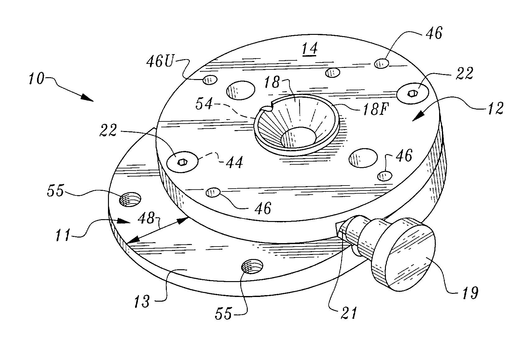
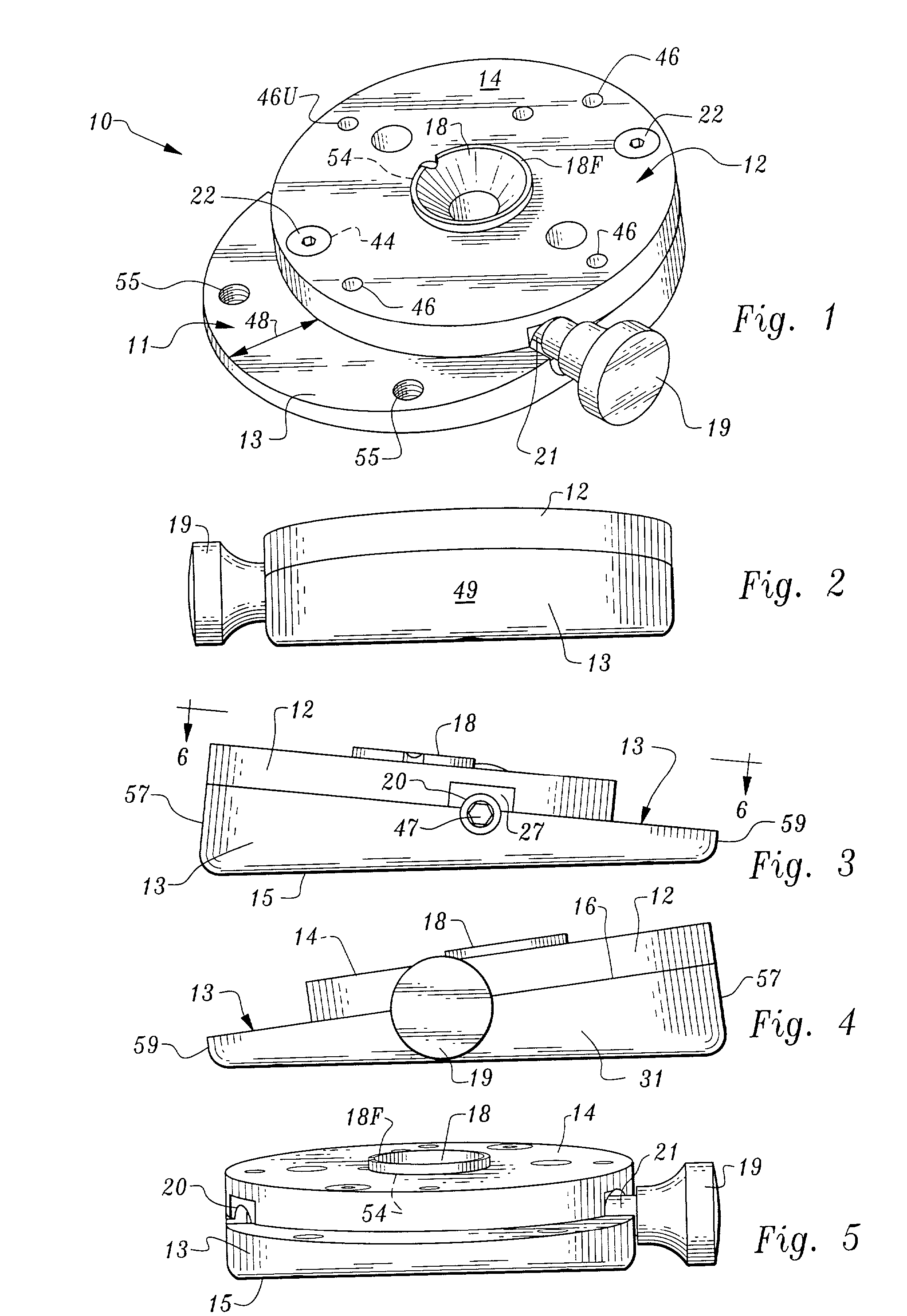
[0041] The discussion now turns to FIGS. 1-7 which pertains to the above-the-knee first embodiment coupler 10 and in particular FIG. 1 to start. Lower plate 11 is seen to be a machined metal element or one of cast rigid high tolerance plastic such as of polycarbonate or Delrin.RTM.). Lower plate 11 is connected to upper plate 12 by a pair of spaced bolts 22--preferably Allen screws, through tapped bores 44 seen in FIG. 1. These bores 44 communicate through the upper plate 12 to the lower plate 11 to threaded bores 62. As seen in FIG. 7, for the aligned combination to be designated 44 / 62 to receive the aforementioned Allen screws 22, to mate the upper plate to the lower plate. The shaft tip of the bolts 22 are not seen in FIG. 7 since they do not consume all of the threads available, and are thus recessed inwardly. Spaced bores 46U attaches the engaged upper plate 12, to a cup-shaped pin guide such as 50 shown in FIG. 22 from the bottom surface 16 of the upper plate 12, by using rece...

second embodiment

[0074] FIG. 20 is an exploded view of the Since the purpose of this view is merely to illustrate how the various aspects of the invention, and the pin guide which is not part of the invention interrelate and go together, the parts have been left unnumbered for ease of understanding.

USE OF THE INVENTION

[0075] FIGS. 21 and 22 illustrate the interconnection of various parts to provide prosthesis walking ability for a person. FIG. 21 provides the same information but the set up incorporates a prior art pin guide. Note however, that the two pin guides are both designated 50, since they form no part of this invention. The pin guide 50 of FIG. 22, however is the subject matter of a design application filed by this applicant, prior to the filing of this utility patent application.

[0076] In these two figures a leg stump of a human 64 is seen to disposed in a stump liner 65--conventional item found in the marketplace--and which stump liner has a T-nut 56 disposed therein to receive the conve...


PUM


Abstract

A device to couple a prosthesis to a human leg stump above-the-knee in a first embodiment, and below the knee in the second embodiment. The device has an upper and a lower plate, the connecting mechanism being disposed in the lower plate. The upper plate is round and the same in both embodiments, but for above-the-knee junctions, the lower plate is elliptical while for below-the-knee junctions, the lower plate is round and of the same diameter as the upper plate. The operative connection is achieved by use of a guillotine, whose horizontally disposed blade engages one of a plurality of grooves on a locking stud. The movement of the spring-loaded guillotine is controlled by a retractable release pin to permit the guillotine to engage in or disengage the groove to which is disposed.

Description

[0001] This invention relates to prosthetic devices and more particularly to a coupler which in one embodiment is used above-the-knee and in the second embodiment is used below-the-knee to connect the leg stump disposed within a liner and sleeve to the prosthesis.[0002] This invention relates to an improved coupler for releasably connecting a prosthetic device in the form of an artificial leg to a sleeve which receives the stump of an amputee's limb. A locking stud, engages both the sleeve and the prosthesis through the interposed attachment coupler. The coupler of this invention uses a retractable release pin or guillotine which engages one of a plurality of grooves formed within the locking stud and which is projecting from the sleeve holding the leg stump of the user.[0003] In the past there have been several patented inventions that relate to below-the-knee prosthesis couplers. All of these incorporate some type of release pin to disengage the locking stud or stud lock from the ...

Claims


Application Information

Patent Timeline
Patent Type & Authority Applications(United States)
IPC IPC(8): A61F2/00A61F2/50A61F2/60A61F2/78A61F2/80
CPCA61F2/78A61F2/80A61F2002/305A61F2220/0025A61F2002/607A61F2002/7875A61F2002/5073
Inventor LUND, ARNOLD A.
Owner LUND ARNOLD A
Why Eureka
Try Eureka