
System and method for determining the load state of a motor vehicle

a technology for determining the load state and motor vehicles, which is applied in the direction of braking systems, process and machine control, instruments, etc., can solve the problems of inability to accurately estimate the load of motor vehicles, inability to use them, and inability to meet the requirements of operation

Inactive Publication Date: 2003-07-31
ROBERT BOSCH GMBH
View PDF7 Cites 25 Cited by
  • Summary
  • Abstract
  • Description
  • Claims
  • Application Information

AI Technical Summary

Benefits of technology

[0023] Beyond merely assessing the load state, the assessment system may increase the traffic safety of the vehicle by emitting a command signal according to the assessed load state, the system further including an actuator which influences an operating state of the motor vehicle according to the command signal.
[0034] Within the framework of this influencing step, the transverse acceleration and or the cornering speed may be limited to a corresponding maximum value, thereby preventing rollover of the vehicle.

Problems solved by technology

This serves to guarantee the traffic safety of vehicles, since at inadmissible loads, there exists a threat that devices on the vehicle that are important to the operation may fail.
To be sure, a driver who has not loaded his vehicle at all does not have to worry about his load state, but situations occur often enough, just about generally in the case of commercial vehicles, but also in the case of transporting with passenger cars, in which the driver is no longer able adequately to estimate the loading of his motor vehicle.
This device has the disadvantage that its application is limited to vehicles having air pressure spring systems, which excludes its use in most passenger cars.
Besides, considerable inaccuracies may arise by calculating the vehicle weight from the gas pressure, such as by temperature influences or by deterioration-related influences on the gas.

Method used


Image

  • System and method for determining the load state of a motor vehicle
  • System and method for determining the load state of a motor vehicle
  • System and method for determining the load state of a motor vehicle

Examples


Embodiment Construction

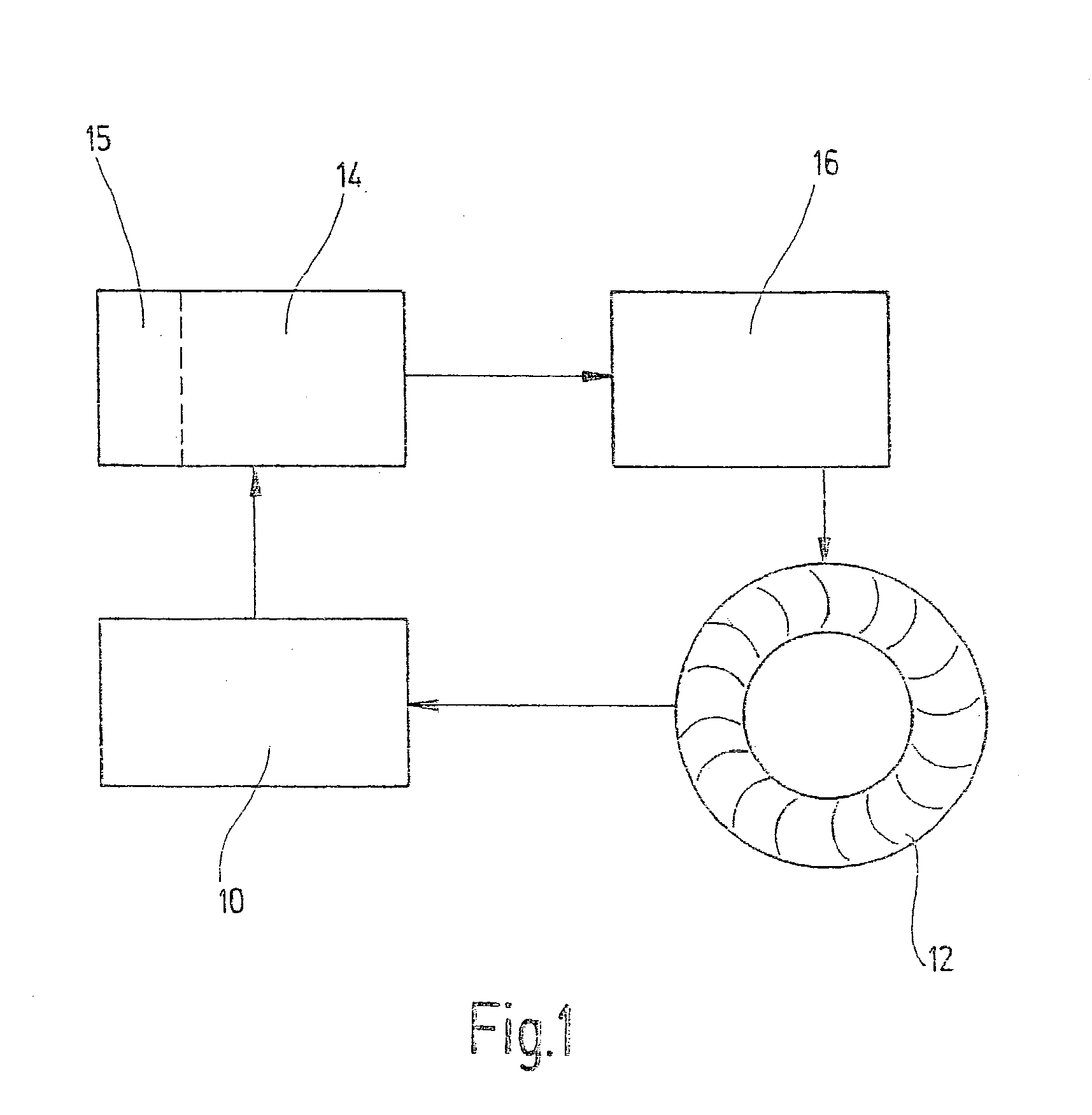
[0042] FIG. 1 shows a block diagram of the system according to the present invention. A sensor device 10 is assigned to a wheel 12, the wheel 12 being shown as representative of the wheels of a vehicle. Sensor device 10 is connected to an assessment system 14 for processing signals from sensor device 10. Assessment system 14 includes a memory device 15 for storing recorded values. Assessment system 14 is also connected to an actuator 16. This actuator, in turn, is assigned to wheel 12.

[0043] In the example shown, sensor device 10 here records the center of tire force and the wheel speed of wheel 12. The recordings resulting from this are transmitted to assessment system 14 for further processing. For example, the wheel contact forces mentioned are ascertained in assessment system 14 from a detected deformation of the tire. This can be accomplished by using a characteristic curve stored in a memory unit.

[0044] In assessment system 14, the load state of the vehicle may be assessed fro...


PUM


Abstract

A system for assessing the load state of a motor vehicle having at least one wheel (12) includes at least one sensor device (10), which records a quantity proportional to the vehicle weight and emits a signal (Si, Sa) representing the quantity, and an assessment system (14), which processes the signal (Si, Sa) representing the recorded quantity, and assesses a load state of the vehicle according to the result of the processing. According to the present invention, the sensor device (10) is a wheel-force sensor device (10) assigned to the at least one wheel (12) which records, as a value proportional to the vehicle weight, the center of tire force of the respective wheel (12) acting essentially between the road surface and the center of tire surface. The present invention also relates to a corresponding method.

Description

[0001] The present invention relates to a system for assessing the load state of a motor vehicle having at least one wheel, including: at least one sensor device which records a quantity proportional to the vehicle weight and emits a signal representing the quantity, and an assessment system which processes the signal representing the recorded quantity, and according to the results of the processing, assesses a load state of the vehicle.[0002] The present invention also relates to a method for assessing the load state of a motor vehicle having at least one wheel, preferably for being executed by a system according to the present invention, which method includes the following steps: Recording a quantity proportional to the vehicle weight, processing the recorded quantity, and assessing the load state of the vehicle according to the result of the processing.BACKGROUND INFORMATION[0003] Motor vehicles are normally assigned a maximum load or a maximum gross weight, exceeding which cance...

Claims


Application Information

Patent Timeline
Patent Type & Authority Applications(United States)
IPC IPC(8): B60T8/22B60C19/00B60P5/00B60R16/02B60T8/00B60T8/172B60T8/174B60T8/175B60T8/1755B60T8/18B60T8/24B60T8/58G01G19/08
CPCB60C19/00B60T8/1725B60T8/17551B60C2019/005B60T8/58B60T2240/03G01G19/08B60T8/18
Inventor BRACHERT, JOSTHESSMERT, ULRICHPOLZIN, NORBERTSAUTER, THOMASWANDEL, HELMUT
Owner ROBERT BOSCH GMBH
Learn More