
Centrifuge with removable core for scalable centrifugation

a centrifuge and core technology, applied in centrifuges, centrifugal force sediment separation, separation processes, etc., can solve the problems of not being able to accommodate the varying volumetric sizes of users, not being suited for linear scale separation, and not being able to utilize the same centrifuge system to accommodate the varying volumetric sizes

Inactive Publication Date: 2003-06-19
ALFA WASSERMANN INC
View PDF0 Cites 39 Cited by
  • Summary
  • Abstract
  • Description
  • Claims
  • Application Information

AI Technical Summary

Benefits of technology

[0027] It is another objective of the invention to provide replaceable cores of different sizes which can be utilized in the same centrifuge apparatus to change the volumetric capacity of the rotor assembly to allow scale ups or scale downs of product sample to be centrifuged without substantially altering selected separation parameters such as sedimentation path, residence path and flow dynamics.
[0031] In accordance with yet another embodiment, a centrifuge apparatus is operable at certain predetermined parameters depending upon a product to be separated and is usable with a plurality of rotor assemblies wherein a first rotor assembly of said plurality of rotor assemblies has a first residence length such that the product passing through the first rotor assembly during rotation thereof in the centrifuge apparatus achieves a first particle separation of the product and a second rotor assembly of said plurality of rotor assemblies has a second residence length such that the product passing through the second rotor assembly during rotation thereof in the centrifuge apparatus achieves a second particle separation of the product which is a linear change with respect to the first particle separation.
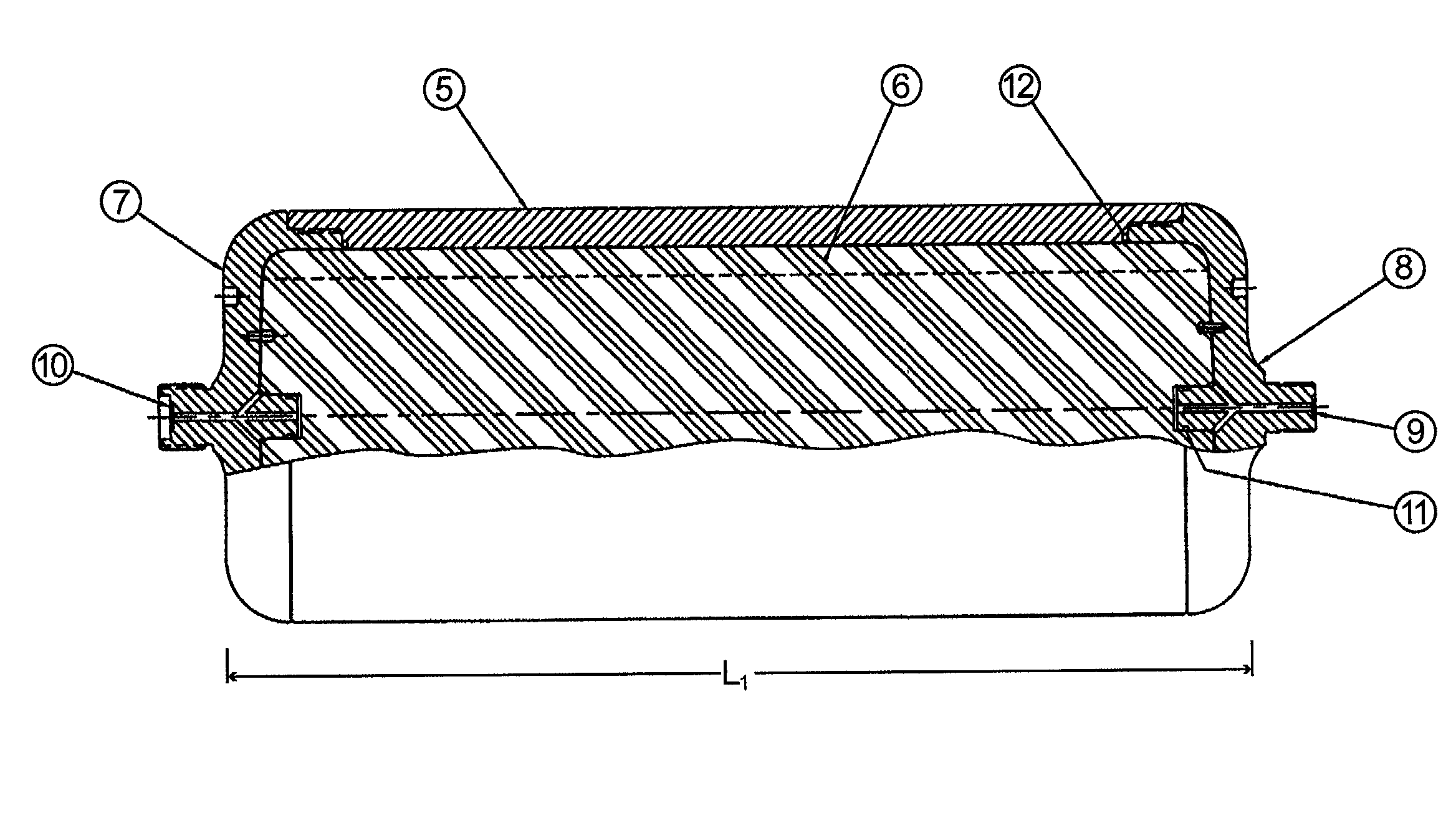
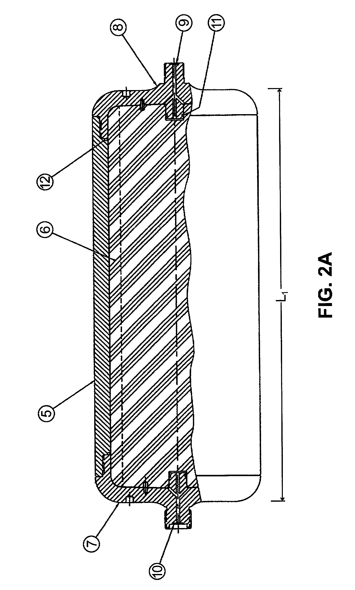
[0032] In accordance with still another embodiment, the rotor assembly capacity is changed by providing more than one core for the rotor assembly. Each core has a different configuration from the other core(s). The use of one core in the rotor assembly will result in a rotor assembly capacity which is different from the rotor assembly capacity when another core is utilized. In one aspect of the invention, the different sized or configured cores can be used to allow the user to operate the centrifuge in different volumes of product samples. In a further aspect of the invention, the cores can be configured so that use of the different cores not only changes the capacity of the rotor assembly but also substantially maintains selected separation parameters in the centrifuge process.
[0033] In accordance with a further embodiment, the rotor assembly includes an outer rotor housing which is formed as a hollow cylinder with threaded end caps to form the outer body of the rotor assembly. An inner core is adapted to be contained within the outer body so as to create a flow path of particles within the rotor assembly. The inner core includes tubular channels for fluid flow and a plurality of fins extend radially from the center core and prevent mixing of the particles during use. As will be explained in more detail below, the size and configuration of the inner core and the fins integrally formed thereto can be altered to change the volume and hence the capacity of the rotor assembly. Moreover, the residence capacity of the rotor assembly can be changed so as to provide linear separation of the particles within the rotor assembly.
[0036] Therefore, the present invention provides a centrifuge apparatus and process in which the volumetric capacity of the rotor assembly can be varied or changed to accommodate different volumes of product sample to be centrifuged. In addition, the present invention provides for replaceable cores with different fin configurations which can be used in the same centrifuge apparatus to change the volumetric capacity of the rotor assembly to allow scale up or scale down of the product sample to be centrifuged without substantially altering selected separation parameters.

Problems solved by technology

However, present centrifuges are not configured to be scalable.
In other words, users cannot utilize the same centrifuge system to accommodate the varying volumetric sizes required for laboratory scale, pilot-scale and large scale needs.
Although the small scale tubular rotor assemblies in the art provide an adequate separation, they are not suited for linear scale separations because of, for example, differences in path length and wall affects (see Rickwood, Preparative Centrifugation: A Practical Approach, 1992, incorporated herein by reference).
A disadvantage of current zonal separation centrifuge systems is that they are not linearly scalable.
In the known art, if a centrifuge system was used in a laboratory scale process, it could not be used in a pilot or large scale process.

Method used


Image

  • Centrifuge with removable core for scalable centrifugation
  • Centrifuge with removable core for scalable centrifugation
  • Centrifuge with removable core for scalable centrifugation

Examples


example 1

[0174] Preparation of Sucrose

[0175] Sucrose crystals (Life Technologies Inc.) were weighed using a top pan balance (two decimal places accuracy) in aliquots of 100 g. Lab water was heated to 60.degree. C. using a heated stir plate. Temperature was measured using a 0-100.degree. C. thermometer. At 60.degree. C. the sucrose was gradually added to the water.

[0176] 1 or 2 liter lots of sucrose were made and pooled, and stock solutions of 60% w / w sucrose were made. The sucrose density was checked with a refractometer for each lot to maintain consistency to within 60.+-.2% sucrose.

example 2

[0177] Preparation of Beads

[0178] Microsphere beads (Bangs Labs Inc.) were diluted in water at concentrations for spectrophotometric analysis. The analysis would be performed on the gradient fractions collected after separation.

[0179] Dilutions were made to give an absorbance peak of 1 AU (absorbance unit) at 280 nm. A scan peak of measurement at approximately 265 nm was chosen for analysis of the beads. This proved to be too concentrated to load to the system and a peak of 0.04 OD 280nm was used. The UV analyses were run at 265 nm, 280 nm and 320 nm. The 280 nm analysis typically showed less variation due to light sensitivity than the analysis at 265 nm. The 320 nm analysis was used to show any light scattering caused by contaminants. A ratio can be calculated between the three analyses to check for contamination of the product to be analyzed. Dilutions were made using p1000 and p200 Gilson pipettes.

[0180] A Perkin Elmer Xpress UV spectrophotometer system was used with 1 cm path, 2...

example 3

[0182] Rotor Assembly and System Setup

[0183] The assembly of both the large scale and pilot-scale ultracentrifuges followed similar protocols. Some of the operational procedures differed due to the different control consoles. Seal assemblies and rotor assemblies were cleaned with water. Ethanol spray was used to remove visible particulate matter from all surfaces. The rotor assemblies were loaded to the centrifuge system, connections made, subsystems checked, and system started according to the instruction manuals.

[0184] In both the large scale and pilot scale systems, the rotor assembly to be tested was filled with water using a peristaltic pump. In addition, a container with a further 2.times.rotor volume of water was attached to the pump inlet and recirculated from the centrifuge top outlet. This allowed for water circulation during the start up phase. In both centrifuge systems, the instruction manuals were followed to perform the following steps: the pump was set to deliver app...


PUM

PropertyMeasurementUnit
Fractionaaaaaaaaaa
Fractionaaaaaaaaaa
Lengthaaaaaaaaaa

Abstract

The present invention relates to a centrifuge apparatus. The centrifuge apparatus is operable at certain predetermined parameters depending upon a product to be separated and is useable with a plurality of rotor assemblies. For example, a first rotor assembly of said plurality of rotor assemblies includes a first core having a first core configuration which is contained within a rotor housing of the first rotor assembly to define a first volume capacity such that the product passing through the first rotor assembly having the first volume capacity during rotation of the first rotor assembly in the centrifuge apparatus achieves a first particle separation of the product. A second rotor assembly of said plurality of rotor assemblies includes a second core having a second core configuration which is contained with a rotor housing of the second rotor assembly to define a second volume capacity such that product passing through the second rotor assembly having the second volume capacity during rotation of the second rotor assembly in the centrifuge apparatus achieves a second particle separation of the product. It is observed that the second particle separation is a linear change with respect to the first particle separation.

Description

[0001] The present invention is directed to centrifuge equipment utilizing a removable core which can be replaced with another core of different dimensions to obtain directly linear scale process results for a particulate protein separation and purification protocol. More particularly, the invention provides a centrifuge rotor assembly comprising means for adjusting the volume of the rotor assembly to accommodate, for example, large-scale, pilot-scale and laboratory-scale centrifugation needs.[0002] Documents cited herein in the following text are incorporated by reference.[0003] In the biological and chemical sciences, there is often a need to separate particulate matter suspended in a solution. In a biological experiment, for example, the particles typically are cells, subcellular organelles and macromolecules, such as DNA fragments. A centrifuge is routinely used to perform the separation of these components from a solution.[0004] The types of experiments that can be performed wi...

Claims


Application Information

Patent Timeline
IPC IPC(8): B04B1/00B04B5/04B04B7/08B04B13/00
CPCB04B1/00B04B5/0442B04B5/10B04B2005/0464B04B7/12B04B13/00B04B7/08
Inventor MERINO, SANDRA PATRICIADALESSIO, STEVEN J.OTTEN, ROBIN ROY LOUIS RUDY
Owner ALFA WASSERMANN INC
Learn More