
Fueling device of fuel tank

a fuel tank and fuel pump technology, applied in the direction of packaging goods, containers preventing decay, applications, etc., can solve the problems of reducing the sealing property of the gasket, affecting the sealing effect, and difficult to uniformly apply the torque, so as to facilitate the opening and closing of the filling opening scc, reduce the diameter of the gasket gs, and improve the sealing effect.

Inactive Publication Date: 2003-04-24
TOYODA GOSEI CO LTD
View PDF5 Cites 17 Cited by
  • Summary
  • Abstract
  • Description
  • Claims
  • Application Information

AI Technical Summary

Benefits of technology

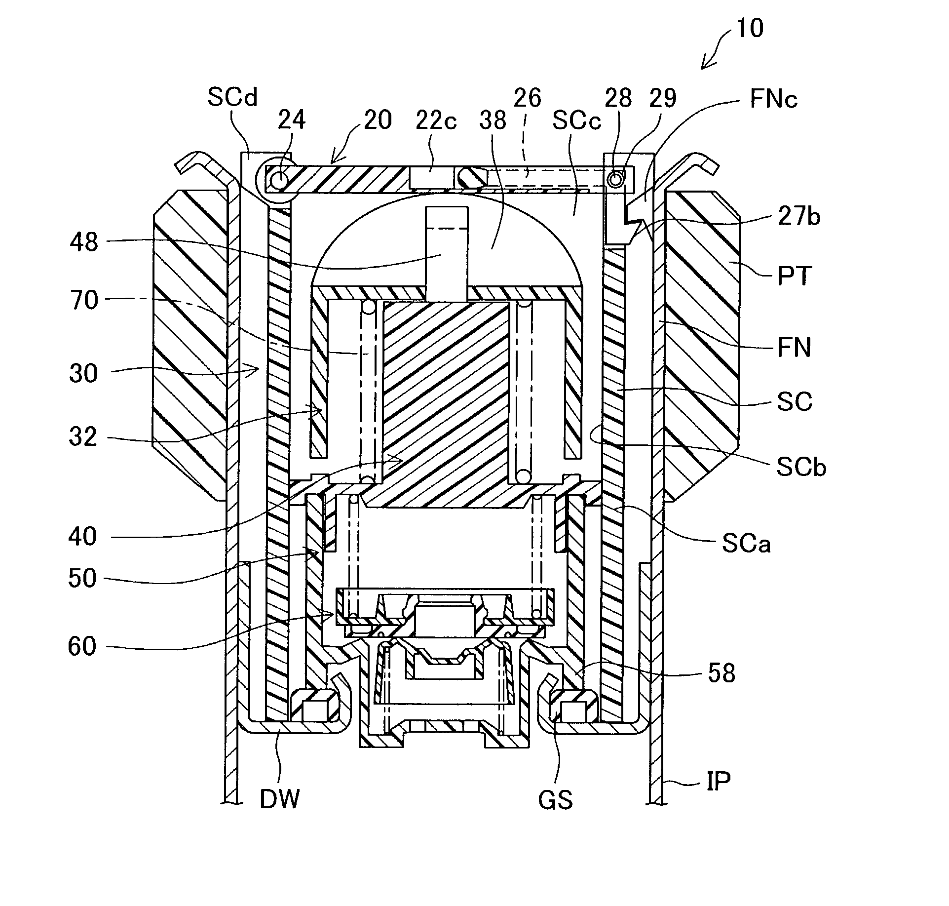
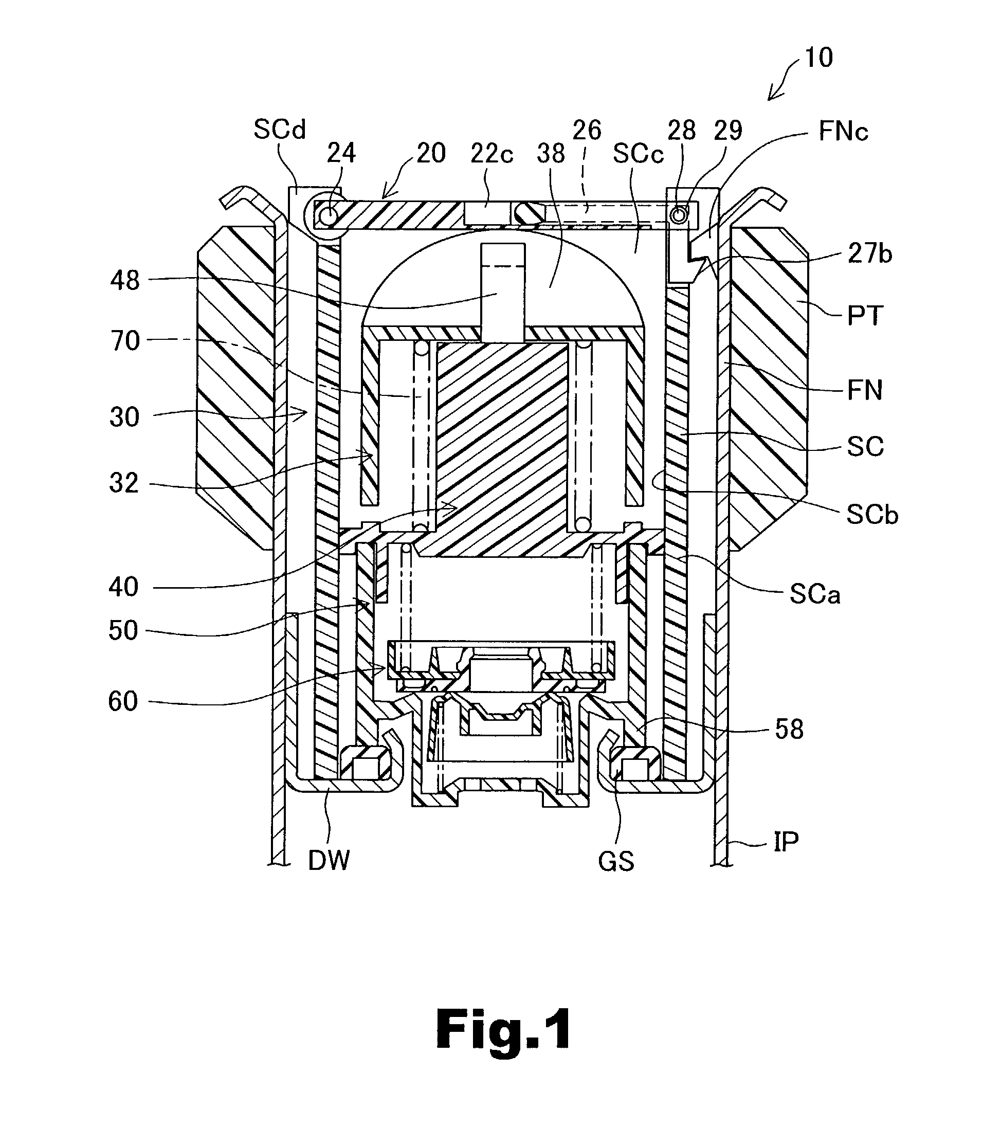
[0011] Filling can be conducted by opening the cover and pulling the cap up, and the operation of opening and closing the filling opening is facilitated because multiple rotation operations or large rotation torque, which were necessary to open the conventional caps, are not required.
[0012] Even when the upper portion of the fuel filler pipe is subjected to large external forces produced, for example, when the vehicle rolls over, the sealing property is not lost because the cap is buried in and protected by the fuel filler pipe.
[0013] Further, because sealing component is disposed inside the fuel filler pipe, the diameter thereof can be decreased by comparison with that of the structure in which it is attached on the outer periphery of the cap, as was explained with reference to the prior art technology. Therefore, the quantity of fuel evaporated from the gasket surface due to fuel-induced swelling of the gasket can be reduced.
[0014] Here, pressing mechanism, for example, an elastic member such as a spring, can be used between the cover and sealing component to employ the force which acts in the direction of closing the cover as the force pressing against sealing component. Alternatively, the same object can be attained by setting dimensions such that sealing component is pressed when the cover is closed. In this case, when a spring is used, setting the sealing force of sealing component by the pressing force of the spring makes it possible to obtain a stable sealing force, the pressing force of the spring being easily adjustable.
[0015] In the preferred embodiment of the present invention, a structure can be employed in which the cap comprises a cap upper body receiving the force acting in the direction of closing the cover and a cap lower body to which sealing component is attached, and the spring is disposed so as to transmit the force acting in the direction of closing the cap upper body to the cap lower body. The cap lower body can have a structure comprising a cap linking body for supporting the spring between the cap upper body and the cap lower body and for linking to the cap upper body so as to maintain the distance from the cap upper body within the prescribed range.
[0022] Further, in the preferred embodiment of the present invention, a structure can be employed in which the fueling device comprises a support inner cylinder attached inside the fuel filler pipe and supporting the cap and this support inner cylinder has a sealing member attached thereto. With such a structure, if the support inner cylinder is taken out of the fuel filler pipe, the sealing member can be removed together with the support inner cylinder and maintenance of the sealing member can be facilitated.

Problems solved by technology

When the fuel cap is screwed onto the opening of the filling neck, the gasket provides air-tight sealing force, while subject to torque caused by rotating friction force, against the filling neck.
Applicant has found that such torque is not readily applied uniformly across the gasket as a whole, and complicates efforts to improve the sealing properties.
Additionally, the gasket is removed with the fuel cap when the fuel cap is placed in the open position, resulting in stains and damage to the seal surface of the gasket.
In such cases, not only are the sealing properties of the gasket compromised, but there is greater friction resistance with the gasket, tending to result in greater operating force required to open and close the fuel cap.
Furthermore, when a fueling gun is introduced into the inlet opening, the fueling gun strikes the inlet opening, damaging the seal in the opening in contact with the gasket.
The sealing properties are compromised in this case as well due to possible damage to the gasket.

Method used


Image

  • Fueling device of fuel tank
  • Fueling device of fuel tank
  • Fueling device of fuel tank

Examples


Embodiment Construction

has been provided for the purpose of explaining the principles of the invention and its practical application, thereby enabling others skilled in the art to understand the invention for various embodiments and with various modifications as are suited to the particular use contemplated. The foregoing detailed description is not intended to be exhaustive or to limit the invention to the precise embodiments disclosed. Modifications and equivalents will be apparent to practitioners skilled in this art and are encompassed within the spirit and scope of the appended claims.


PUM

PropertyMeasurementUnit
angleaaaaaaaaaa
closing forceaaaaaaaaaa
distanceaaaaaaaaaa

Abstract

A fueling device 10 of a fuel tank comprises a cover 20 which is provided with an operation lever 26 operated to open and close a filling opening SCc, and which opens and closes the filling opening SCc according to the opening / closing operation of the operation lever 26, a fuel cap 30 having a structure such that it is fitted in a buried state in an inlet pipe IP and taken out from the inlet pipe, a gasket GS interposed between the fuel cap 30 and the inner wall of inlet pipe IP, and a spring 70 interposed between the fuel cap 30 and gasket GS and pressing the gasket GS against the sealing surface by a force acting in the direction of closing the cover 20 via the fuel cap 30, while increasing the pressing force. The fueling device 10 has high sealing property against large external forces applied to the upper part of fuel filler pipe.

Description

[0001] This application claims the benefit of and priority from Japanese Application No. 2001-307824 filed Oct. 3, 2001, the content of which is incorporated herein by reference.[0002] 1. Field of the Invention[0003] The present invention relates to a fueling device for fueling a fuel tank through a passage of a fuel filler pipe.[0004] 2. Description of the Related Art[0005] In conventional fueling devices for fueling a fuel tank through a filler pipe, the fuel cap is open when fuel is supplied through a fuel filler pipe. The fuel cap has a sealing member which, in a closed position, is inserted between the fuel cap and an inlet opening of the fuel filler pipe to prevent fuel vapor in the fuel tank from escaping into the atmosphere. The sealing member is in the form of a gasket extending around the periphery of a cylindrical casing main body. When the fuel cap is screwed onto the opening of the filling neck, the gasket provides air-tight sealing force, while subject to torque caused...

Claims


Application Information

Patent Timeline
Patent Type & Authority Applications(United States)
IPC IPC(8): B60K15/04B60K15/05B65D51/00F02M37/00
CPCB60K15/0406B60K15/05Y10S220/33B60K2015/0422B60K2015/03547
Inventor HAGANO, HIROYUKI
Owner TOYODA GOSEI CO LTD
Learn More