
Mat

a technology of mats and mats, applied in the field of mats, can solve the problems that the mat cannot be used later on, and achieve the effect of convenient us

Inactive Publication Date: 2003-01-23
PRINZMETAL JAN
View PDF3 Cites 52 Cited by
  • Summary
  • Abstract
  • Description
  • Claims
  • Application Information

AI Technical Summary

Benefits of technology

The technical effect of this patent is to improve the design of mats for exercise purposes by making them more flexible, comfortable, and easier to use. Additionally, they have added removable, adjustable straps that can be easily customized for different users. This makes it much better suited for people who are looking for a new way to work out or want something more challenging than what their current gym offers.

Problems solved by technology

The technical problem addressed in this patent text needs to be identified by a senior R&D person who has read it through.

Method used


Image

  • Mat
  • Mat
  • Mat

Examples


Embodiment Construction

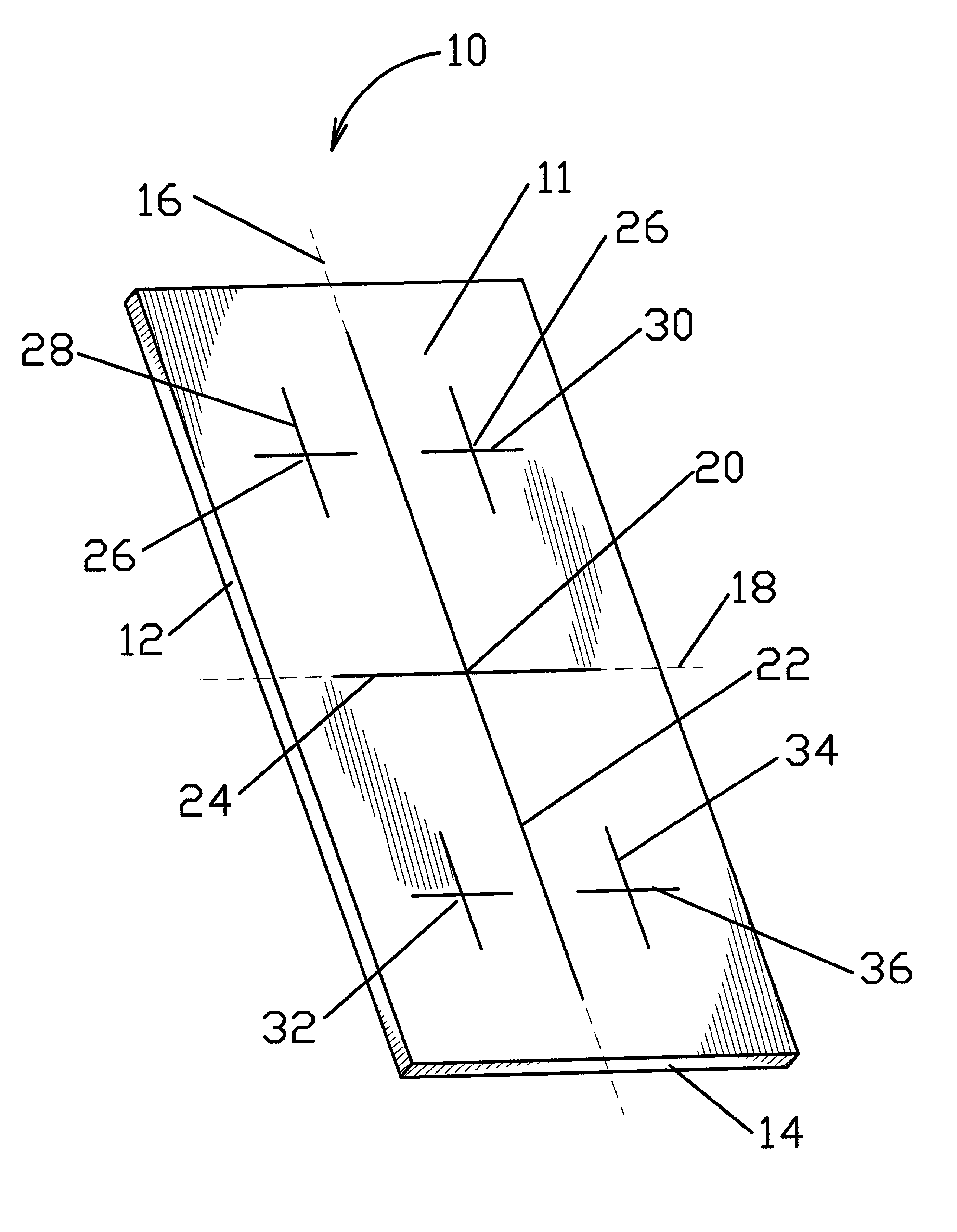
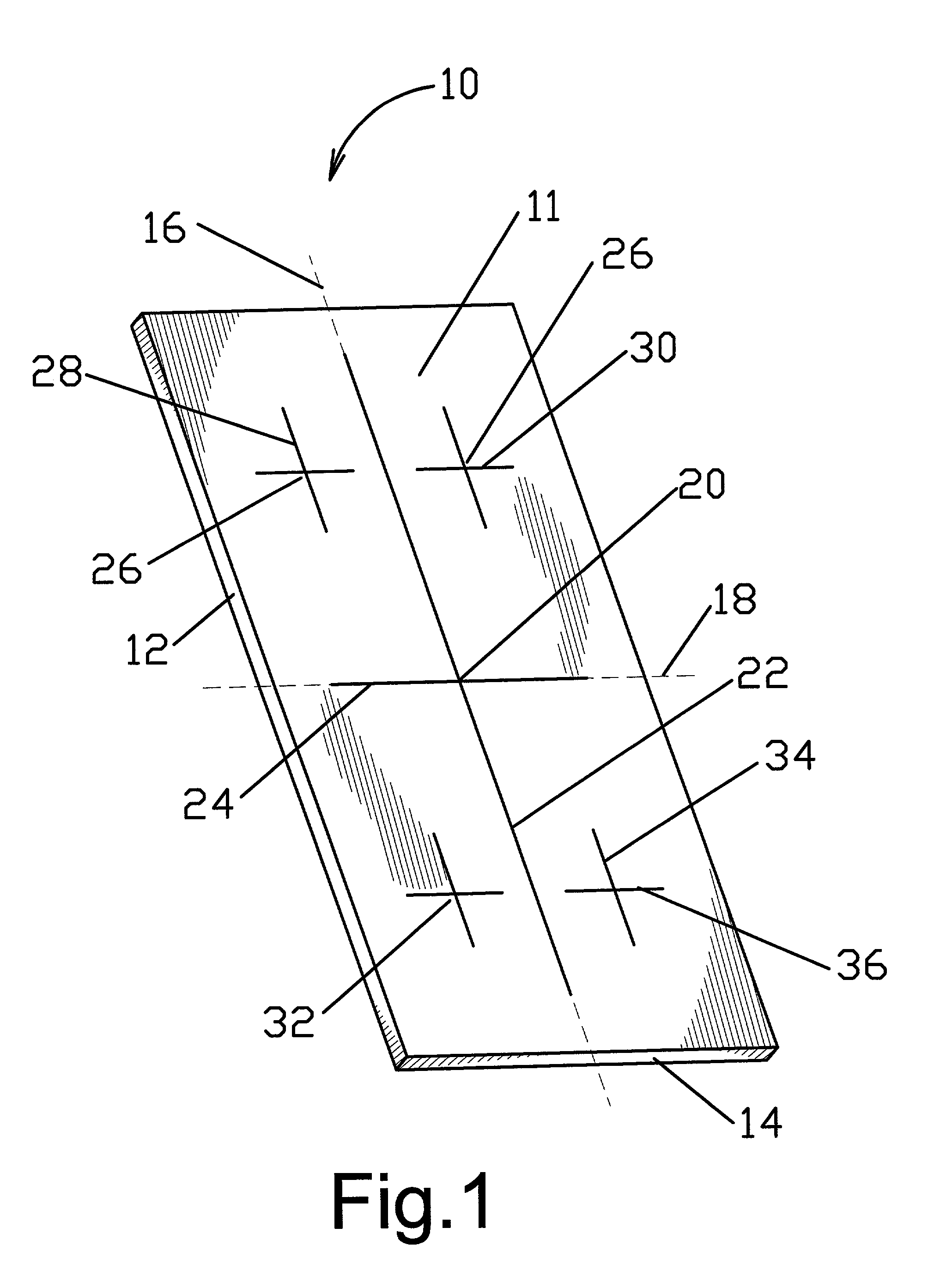
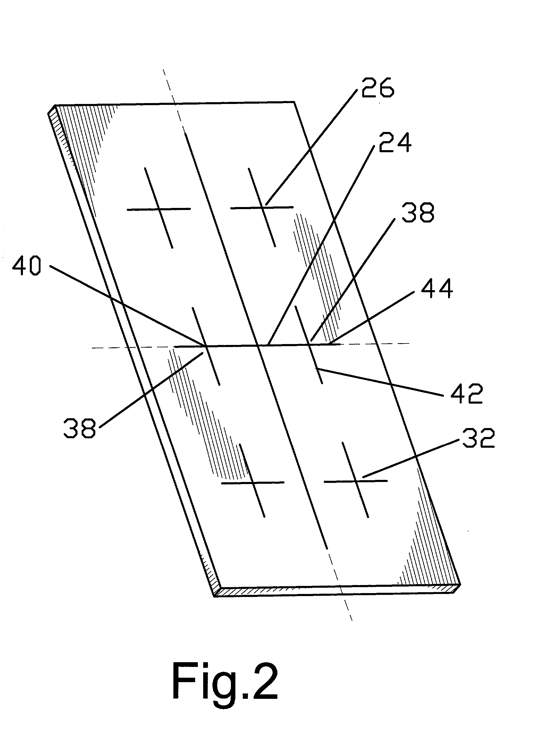
[0014] Referring now to the drawings, FIG. 1 illustrates an exercise mat 10, formed from a pliable sheet 11 and having a size to comfortably accommodate a person thereon. Sheet 11 is formed of any lightweight, cushioning and insulating material, which provides a smooth, unbroken top surface, and has a basically rectangular periphery. The latter is defined by two parallel side edges 12 and two parallel end edges 14, the former being longer than and perpendicular to the latter. One longitudinal and one transversal axes of symmetry 16 and 18, respectively, which intersect in a center of symmetry 20, define geometrically mat 10. In a first variant of the present invention (see FIG. 1), to sheet 11 is added a first alignment strip 22 extending substantially along longitudinal axis of symmetry 16 toward parallel end edges 14 and a second alignment strip 24 extending substantially along transversal axis of symmetry 18 toward parallel side edges 12.

[0015] First and second alignment strips 2...


PUM


Abstract

A mat, adaptable for floor exercises, comprises a pliable sheet having a rectangular periphery. A first alignment strip extends along the longitudinal axis of symmetry of the sheet, while a second alignment strip extends along the transversal axis of symmetry of the sheet. A hand reference zone is disposed at an upper part of the mat, on each side of the first alignment strip and a foot reference zone is disposed at a lower part of the mat, on each side of the first alignment strip. A side reference zone is disposed at the middle of the mat and comprises a vertical and horizontal side strip. Hand and foot reference zones are made of vertical and horizontal hand and foot strips. Above and beneath the horizontal strips of each hand and foot reference zones several parallel targets strips are used. To the left and right of the vertical line of side reference zone several parallel target strips are also used.

Description


Claims


Application Information

Patent Timeline
Owner PRINZMETAL JAN
Learn More