
Distribution cabinet

a technology for distribution cabinets and shelves, applied in the field of distribution cabinets, can solve the problems of large the overall dimensions on the outside, and achieve the effect of reducing the overall dimension of the outside and the excess of small free space on the insid

Inactive Publication Date: 2003-01-16
BERTHOLD SICHERT GMBH
View PDF0 Cites 47 Cited by
  • Summary
  • Abstract
  • Description
  • Claims
  • Application Information

AI Technical Summary

Benefits of technology

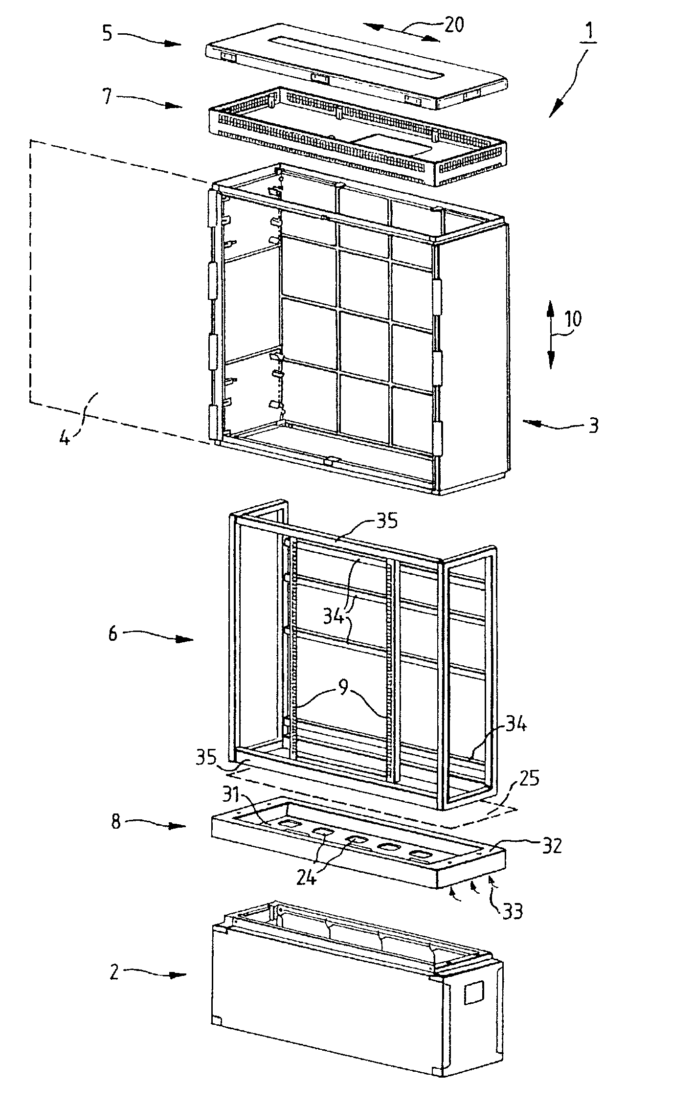
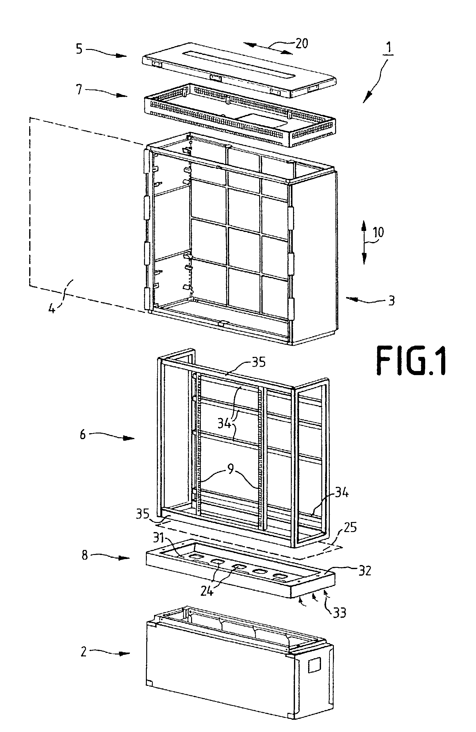
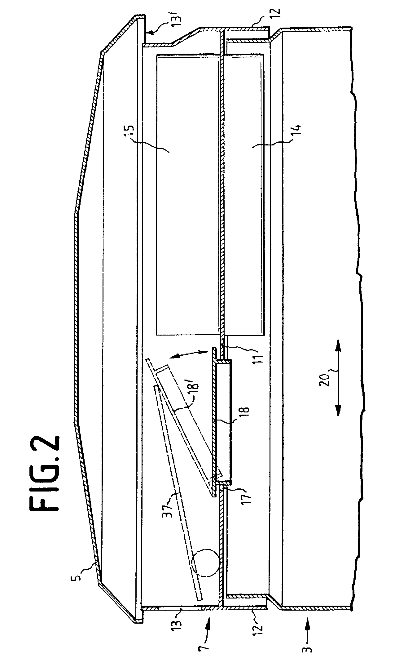
[0013] A distribution cabinet according to the invention may be produced from these known components by the addition of an installation frame which is made up, in particular, of deflected sections of an endless profile. The specific integration of the profile makes it possible, on the one hand, to simplify the assembly to form a--three-dimensional--inst-allation frame to a very considerable extent and, in addition, to facilitate the optional fitting of EMC shielding and / or the production of a double-shell wall of the distribution cabinet for ventilation and cooling purposes.
[0043] This is intended to allow existing distribution cabinets to be converted without operation being interrupted in that the electrical components which are fixed and connected in the installation frame remain there and, in addition, need not be disconnected, but the cover and body can nevertheless be raised off in the upward direction.

Problems solved by technology

However, on account of the greater wall thicknesses which are necessary in this case, and of the outer and inner dimensions being predetermined by standards in the various countries, this would result in excessively small free spaces on the inside and overall dimensions on the outside.

Method used


Image

  • Distribution cabinet
  • Distribution cabinet
  • Distribution cabinet

Examples


Embodiment Construction

[0007] a) Technical Object

[0008] The object of the present invention is thus to provide a distribution cabinet and an assembly kit for producing such a distribution cabinet, the distribution cabinet consisting at least partially of plastic and nevertheless providing sufficiently good shielding against electromagnetic radiation, on the one hand, and a sufficient cooling capability, on the other hand.

[0009] b) Solution of the Object

[0010] This object is achieved by the features of claim 1. Advantageous embodiments can be gathered from the subclaims.

[0011] Up until now, distribution cabinets produced from plastic usually comprised a base box, which was usually open on the top side and also on the underside, since the underground cables were introduced into the base unit, a body, which was positioned on the base and on which one or two doors or flaps for opening the body were provided, for the purpose of installing or maintaining and checking the electrical units in the interior of the ...


PUM


Abstract

A distribution cabinet (1) for accommodating weak-current distribution installations, in particular for arranging outdoors, having a base box (2), an outer cabinet body (3) with at least one door (4), a cabinet cover (5), and an inner installation frame (6), the installation frame (6) being made up of profile sections (50), of which the cross-sectional shapes has two insertion pockets (51a,b), of which the insertion directions (52a,b) run at right angles to one another.

Description

I. APPLICATION AREA[0001] The invention relates to a distribution cabinet which is usually set up outdoors and accommodates the distribution installations for weak-current systems, for example telephone systems, with associated power-supply devices and cable-terminal / -connection devices for a certain area.II. TECHNICAL BACKGROUND[0002] Nowadays--in addition to having sufficient structural stability and resistance to vandalism, etc.--such distribution cabinets have to satisfy further requirements, for example excessive electromagnetic radiation must not be emitted to the surroundings, and, for use in warmer countries in particular, the temperatures in the interior of the distribution cabinet must not rise to too high a level, despite the heat-emitting electrical subassemblies accommodated there, nor must they drop to too low a level.[0003] Such distribution cabinets are basically produced either from metal or from plastic, plastic combining the advantage of less expensive production ...

Claims


Application Information

Patent Timeline
Patent Type & Authority Applications(United States)
IPC IPC(8): H02B1/01H02B1/50H02B1/56H04Q1/14H05K7/18
CPCH02B1/013H02B1/50H02B1/565H04Q1/14H04Q2201/06H04Q2201/10H04Q1/035H04Q1/116H04Q1/025
Inventor IRMER, GUNTER
Owner BERTHOLD SICHERT GMBH
Learn More