
Custom-moldable support for patellar tendinitis

a patellar tendinitis and support technology, applied in the field of custom-molded support, can solve the problems of patellar tendinitis, patellar tendinitis, insufficient pain relief of prior art methods for treating patellar tendinitis,

Inactive Publication Date: 2002-10-10
BSN MEDICAL INC
View PDF0 Cites 21 Cited by
  • Summary
  • Abstract
  • Description
  • Claims
  • Application Information

AI Technical Summary

Benefits of technology

[0007] It is another object of the invention to provide a knee pad assembly which provides concentrated, radially-directed support to the knee area without compromising circulation of blood to the injured area and to the lower leg.
[0008] It is another object of the invention to provide a knee pad assembly that hardens in the presence of moisture to form a very rigid yet very lightweight protective pad.
[0009] It is another object of the invention to provide a knee pad assembly that can be quickly and easily positioned on and removed from a wearer's forearm by the wearer.

Problems solved by technology

As discussed below, each of these activities involves repetitive use of the same muscle groups and tendons in the legs, which often leads to the inflammation and tearing of the tendons associated with patellar tendinitis.
Prior art methods available for treating patellar tendinitis often fail to provide adequate pain relief.
While such devices may provide some degree of generalized support to the injured area, they have limited effectiveness because they provide such support in a manner that inhibits adequate blood flow to the lower limb, and fails to direct concentrated support to the injured area.
Those straps which do provide additional padding over the inflamed area are likewise inadequate because the padding is typically so thick that the strap will not conform to the shape of the lower leg without applying an increased amount of pressure over the injured area.
This increased pressure causes the padding to compress against the lower leg, and can compromise circulation in the same manner as seen with unpadded straps.
Such padded and unpadded elastic straps not only fail to provide concentrated support directly over the injured area, but also fail to provide a secure, custom fit which addresses the unique anatomical needs of the individual wearer.

Method used


Image

  • Custom-moldable support for patellar tendinitis
  • Custom-moldable support for patellar tendinitis
  • Custom-moldable support for patellar tendinitis

Examples


Embodiment Construction

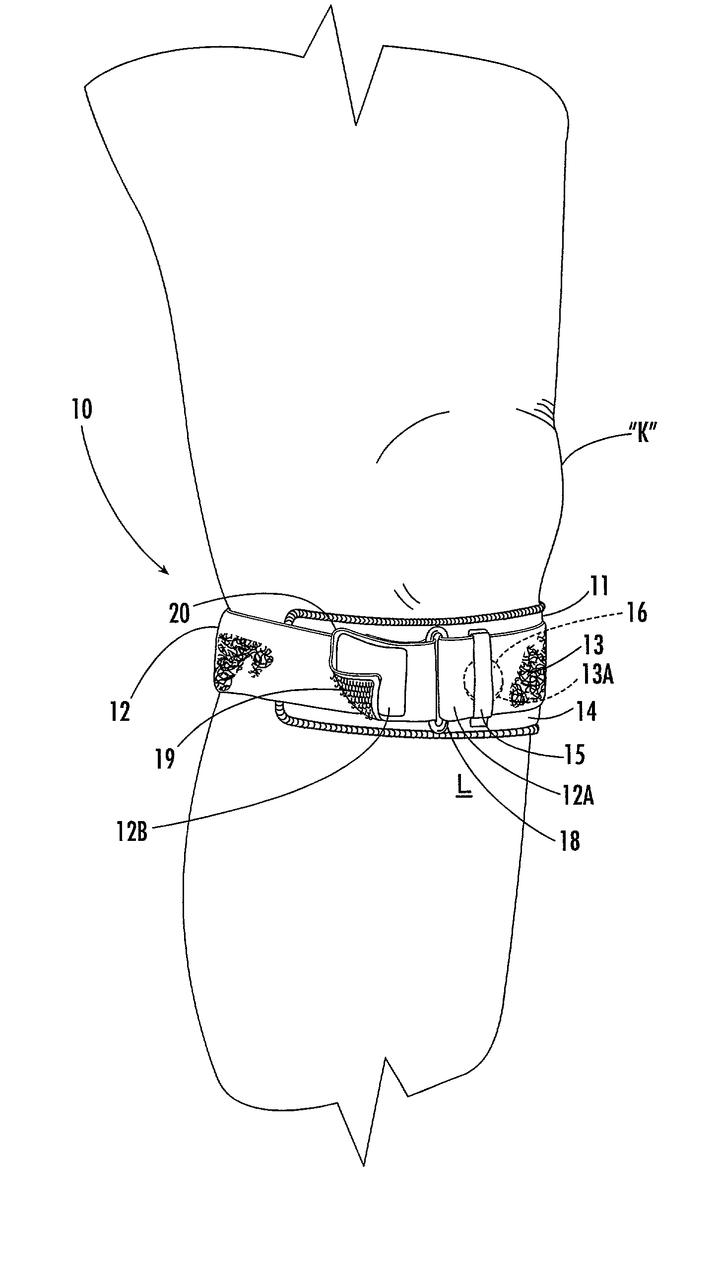
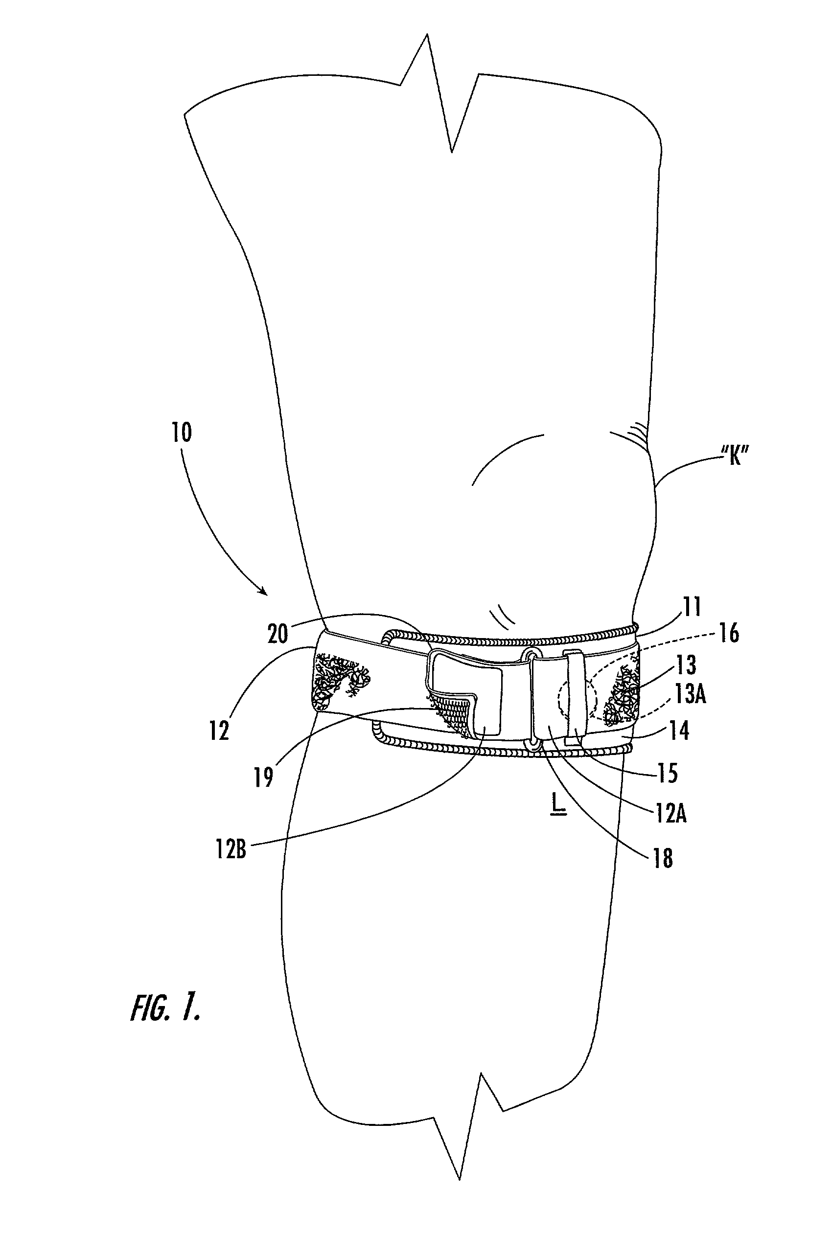
[0047] Referring now specifically to the drawings, a knee pad assembly is illustrated in FIG. 1 and shown generally at reference numeral 10. The assembly 10 includes a pad 11 which, as is described more fully in reference to FIGS. 7, 8 and 9 below, is custom-molded to fit immediately below a wearer's knee "K", and is held in place by an elongate strap 12. Although the strap 12 may be formed from any suitable flexible substance, the strap 12 is preferably formed of a narrow length of elasticized woven or knitted material having a raised, fibrous surface 13 to which a patch of looped material 13 A is attached. The pad 11 has an upper surface 14 to which the ends of a relatively narrow strap loop 15 are sewn. The loop 15 extends across the width of the pad 11 and maintains the pad 11 in place against the lower leg "L". A second patch of hooked material 16 is attached to the upper surface 14 of the pad 11. The strap 12 has a first end 12A to which a D-ring 18 is secured. A third patch o...


PUM


Abstract

A knee pad assembly for relieving the symptoms of patellartendinitis, including a pad adapted for being positioned against and molded onto a lower leg in the region of the knee for lying in closely-conforming relation against and applying radially-directed pressure to the attachment site of the patellar tendon to the patella, to the knee joint, and to at least one epicondyle of the tibia. The pad is hardened into a rigid structure for therapeutic use and includes an initially flexible inner substrate impregnated or coated with a reactive system. The system remains stable when maintained in substantially moisture-free conditions and hardens upon exposure to moisture to form a rigid, self-supporting structure having a shape conforming to the lower leg to which the pad is molded during curing. A flexible cover encloses the substrate, and cooperates with the pad for maintaining the pad in its closely-conforming position against the lower leg.

Description

TECHNICAL FIELD AND BACKGROUND OF THE INVENTION[0001] This invention relates to a custom-molded pad for relief of the symptoms of patellar tendinitis. Patellar tendinitis is the inflamation of the patellar tendon at the point at which it attaches to either the inferior pole of the patella or the tibial tuberosity, or the inflamation of the quadriceps tendon at the point at which it attaches to the superior pole of the patella. Patellar tendinitis is primarily caused by continued stress on the patellar or quadriceps tendons. Although repetitive jumping, such as that which occurs while playing volleyball, is an activity commonly associated with aggravating the onset of patellar tendinitis, there are several other activities that can cause the condition, such as running, walking or bicycling. As discussed below, each of these activities involves repetitive use of the same muscle groups and tendons in the legs, which often leads to the inflammation and tearing of the tendons associated ...

Claims


Application Information

Patent Timeline
IPC IPC(8): A61F13/06
CPCA61F13/062
Inventor DARCEY, THOMAS D.
Owner BSN MEDICAL INC
Learn More