
Water filtration using immersed membranes

a technology of water filtration and membranes, applied in membranes, sustainable biological treatment, biological water/sewage treatment, etc., can solve the problems of affecting the filtering process, and damage to membranes by cleaning methods

Inactive Publication Date: 2002-09-19
ZENON TECH PARTNERSHIP
View PDF32 Cites 14 Cited by
  • Summary
  • Abstract
  • Description
  • Claims
  • Application Information

AI Technical Summary

Problems solved by technology

Unfortunately, while this process preserves a mass balance, the tank water operated at a recovery rate of 95% (ie.
Accordingly, the tank water has a high concentration of pollutants at all times. Operating at a lower recovery rate, 80% for example, results in tank water having a lower concentration of solids but the cost of transporting excess feedwater and then disposing of excess retentate also increases.
These methods are typically performed frequently and thus may influence the filtering process.
In other cases, the tank remains filled and the amount of chemical cleaner in a cleaning event is limited to an amount that is tolerable for the application.
The cleaning methods all damage the membranes over time.
In addition, backwashing with permeate or chemical cleaner interrupts permeation and reduces the yield of the process.
Aeration requires energy which add to the operating costs of a reactor and the resulting circulation of tank water requires significant open space in the tank.
Particularly in large systems, however, loss in production time can be high because it is difficult to drain a large municipal or industrial tank quickly.
In some cases, the tank is raised and fitted with a large number of drains to promote rapid draining but these techniques increase the cost of an installation.

Method used


Image

  • Water filtration using immersed membranes
  • Water filtration using immersed membranes
  • Water filtration using immersed membranes

Examples


example 1

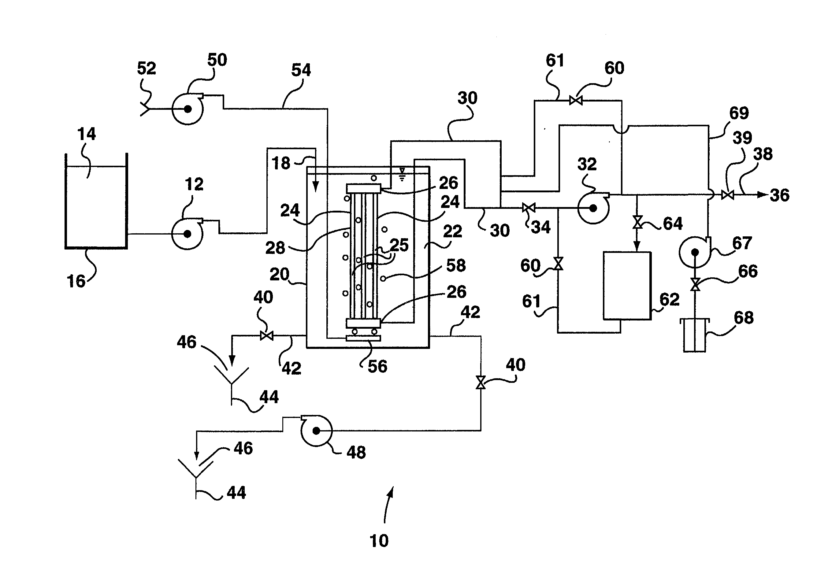
[0085] A submerged membrane reactor according to FIGS. 5A and 5B was modelled using experimental data from tests under a continuous process and assuming that the local flow around the membrane modules is symmetrical in the upstream and downstream directions--ie. the overall tank flow towards the outlet was discounted. The system comprises a tank 16.4 meters long, 3.28 meters wide with an average depth of water of about 2.5 meters. The tank of the reactor contains 12 membrane modules each being a cassette of 8 ZW500 membrane modules. Each cassette is approximately 1.82 meters high, 1.83 meters wide and 0.71 meters long along the flow path and placed in the tank so as to leave approximately 0.75 m between the edge of the cassettes and the long walls of the tank. The cassettes are spaced evenly between the inlet end and outlet end of the tank. Transmembrane pressure is maintained at a constant 50 kPa throughout the model and the permeability of the membranes at any time is determined b...

example 2

[0093] In this example, an actual experimental apparatus was constructed and operated similar to FIGS. 5A and 5B. The dimensions of the tank were as described for the modelling experiments above, but 16 cassettes of 8 ZW500 membrane modules each were installed consecutively 20 cm apart from each other in the direction of the flow path and used with constant aeration. The apparatus was run continuously without deconcentrations at a recovery rate of 91%. The yield was maintained at a constant 93 liters / second with 9.4 liters / second of consolidated retentate continuously leaving the tank. Colour was monitored at each cassette along the tank as an indicator of the concentration of solids at each cassette. As shown in FIG. 17, the concentration of solids increased significantly only in the downstream 20% of the tank with most cassettes operating in relatively clean water.

example 3

[0094] An experiment was conducted with a water filtration system similar to FIGS. 5A and 5B comprising 12 cassettes of 8 ZW 500 modules each. The aeration was linearly increased from about 13.6 Nm.sup.3 / h for each ZW 500 for the first cassette to about 22.1 Nm.sup.3 / h for each ZW 500 for the last cassette. This resulted in a total reduction in system aeration from the usual 1989 Nm.sup.3 / h to 1785 Nm.sup.3 / h, more than a 10% reduction while the rate of membrane fouling remained the same and foaming was considerably reduced. In this experiment, the system recovery was 84% while the water temperature was at 22.5 degrees C.


PUM

PropertyMeasurementUnit
transmembrane pressureaaaaaaaaaa

Abstract

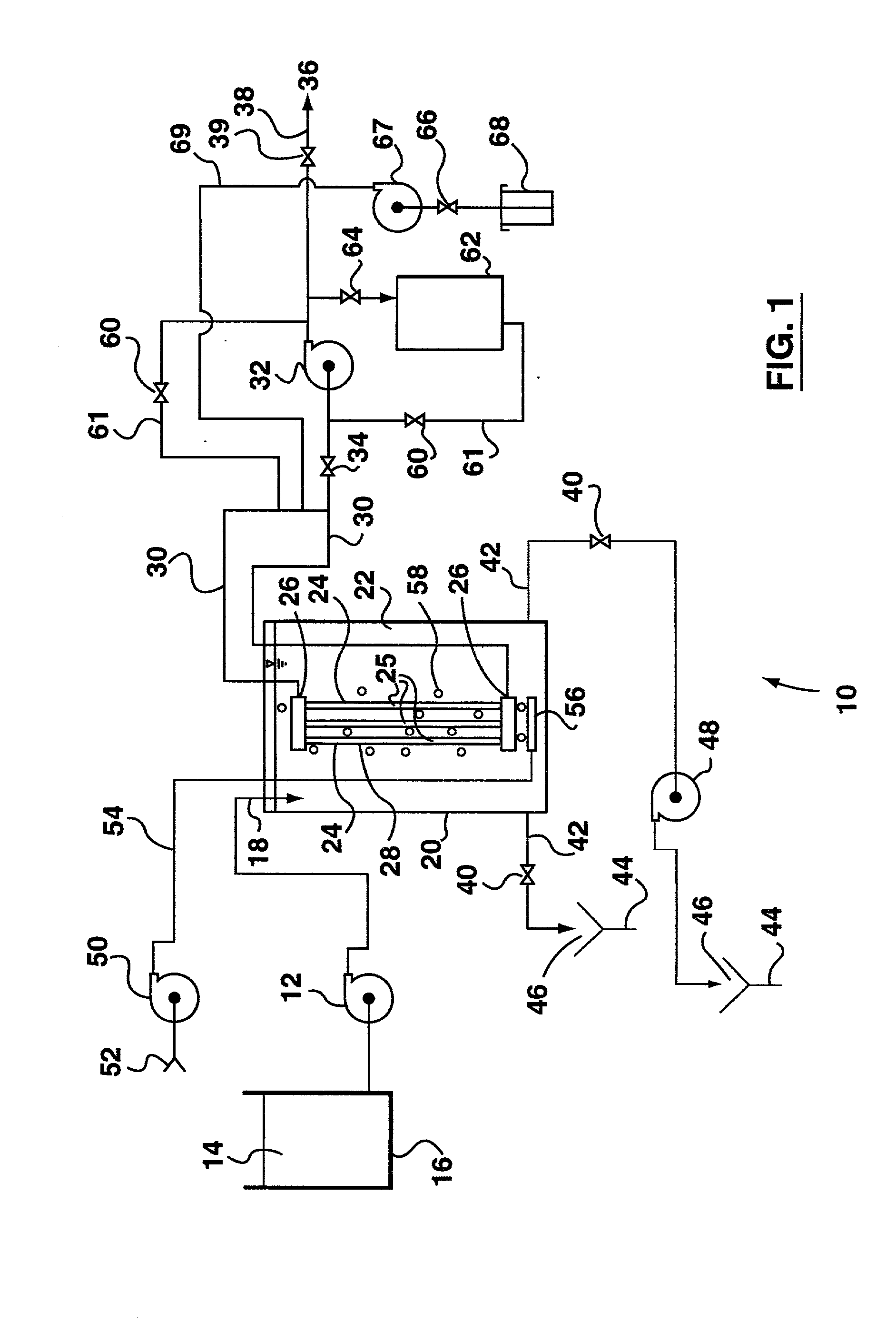
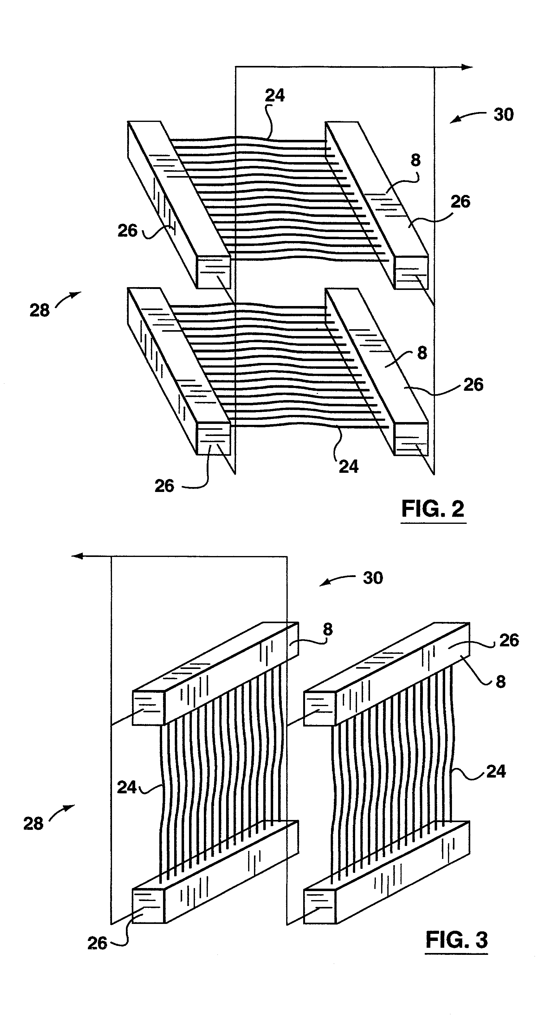
A process for operating filtering membranes submerged in a tank involves, in one aspect, periodically deconcentrating the tank by at least partially emptying and refilling the tank with fresh water while permeation continues. In another aspect, long trains of membranes modules are placed in series along a flow path in the tank. In one embodiment, constant aeration is provided to prevent tank water from by-passing the membrane modules while proving controlled mixing such that the average concentration of solids in the tank is lower than the concentration of solids in the tank near an outlet for removing retentate from the tank. In another embodiment, the membrane modules are arranged in a series of filtration zones between a feed water inlet and a retentate outlet of a tank. Permeate is withdrawn from the filtration zones by separate means associated with each filtration zone. Tank water containing rejected solids flows in a tank flow through the filtration zones, increasing in concentration from one zone to the next. A preferred membrane module has membranes transverse to the tank flow and fills a substantial portion of each filtration zone. With either embodiment, aeration, backwashing or packing density of membranes varies between filtration zones and the flow pattern in the tank may be periodically reversed.

Description

[0001] This is a division of U.S. patent application Ser. No. 09 / 444,414, filed Nov. 22, 1999. The entire disclosure of application Ser. No. 09 / 444,414 is incorporated herein by this reference.FIELD OF THE INVENTION[0002] This invention relates to the use of ultrafiltration or microfiltration membranes to treat water, and more particularly to the design and operation of reactors which use immersed membranes as part of a substantially continuous process for filtering water containing low concentrations of solids, for example for producing potable water.BACKGROUND OF THE INVENTION[0003] Immersed membranes are used for separating a permeate lean in solids from tank water rich in solids. Feed water flowing into a tank containing immersed membranes has an initial concentration of solids. Filtered permeate passes through the walls of the membranes under the influence of a transmembrane pressure differential between a retentate side of the membranes and a permeate side of the membranes. As...

Claims


Application Information

Patent Timeline
Patent Type & Authority Applications(United States)
IPC IPC(8): B01D61/14B01D61/16B01D61/18B01D61/22B01D63/04B01D65/02B01D65/08C02F1/44C02F3/12
CPCB01D61/142B01D61/145B01D61/147B01D61/16B01D61/18B01D61/22B01D63/02B01D63/043B01D65/02B01D65/08B01D2311/04B01D2315/06B01D2321/04B01D2321/16B01D2321/185B01D2321/2066B01D2321/2083C02F1/444C02F3/1273B01D2311/2649B01D2311/14B01D2311/10B01D2311/2661Y02W10/15Y02W10/10B01D61/149B01D63/031B01D2321/167
Inventor COTE, PIERREJANSON, ARNOLDHUSAIN, HADISINGH, MANWINDERADAMS, NICHOLAS
Owner ZENON TECH PARTNERSHIP
Learn More