
Temporary guard rail system

a guard rail and rail system technology, applied in the direction of fencing, building material handling, construction, etc., to achieve the effect of convenient installation, high efficiency and convenient removal

Inactive Publication Date: 2002-08-08
PURVIS HARRISON G
View PDF0 Cites 50 Cited by
  • Summary
  • Abstract
  • Description
  • Claims
  • Application Information

AI Technical Summary

Benefits of technology

[0015] After much research and study into the above mentioned problems, the present invention has been developed to provide a simple and yet highly efficient temporary railing system in accordance with OSHA requirements that can be readily installed when needed and just as readily removed when no longer required.
[0019] In view of the above, it is an object of the present invention to provide a temporary guard rail system that can be readily installed when needed and readily removed when no longer required.
[0020] Another object of the present invention is to provide a temporary guard rail system which may be readily adapted to virtually any configuration encountered in the building construction including roofs, elevated platforms, balconies, stairs, and the perimeter of the floor of the building prior to the construction of the exterior walls or permanent protective railings.
[0021] Another object of the present invention is to provide a temporary guard rail system which may be adapted for installation on soil or asphalt adjacent trenches or other excavations to prevent falls therein.

Problems solved by technology

Typically, a pair or a series of these upright stanchions are attached to the subfloor in locations that present a potential for injury due to falls.

Method used


Image

  • Temporary guard rail system
  • Temporary guard rail system
  • Temporary guard rail system

Examples


Embodiment Construction

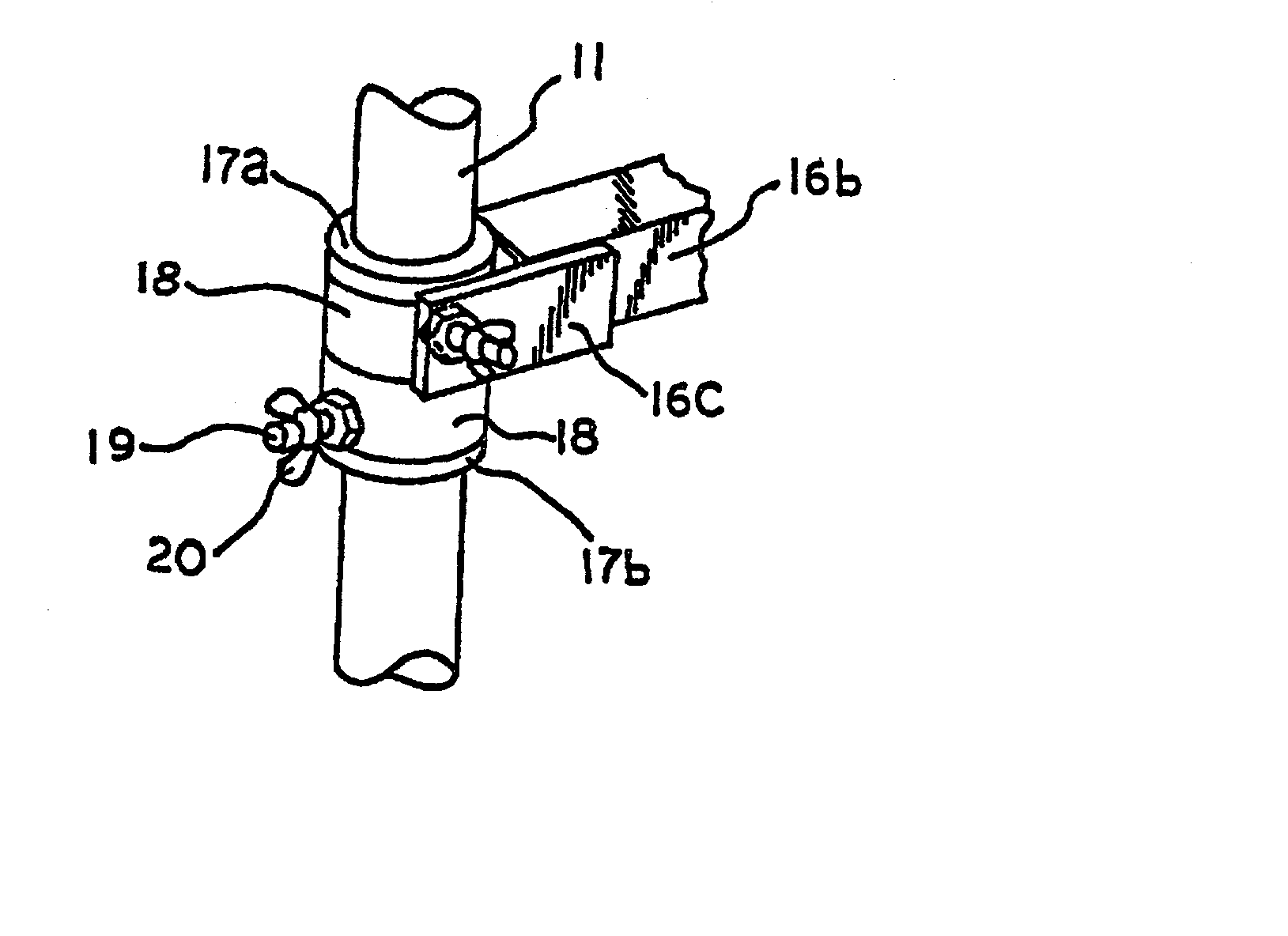
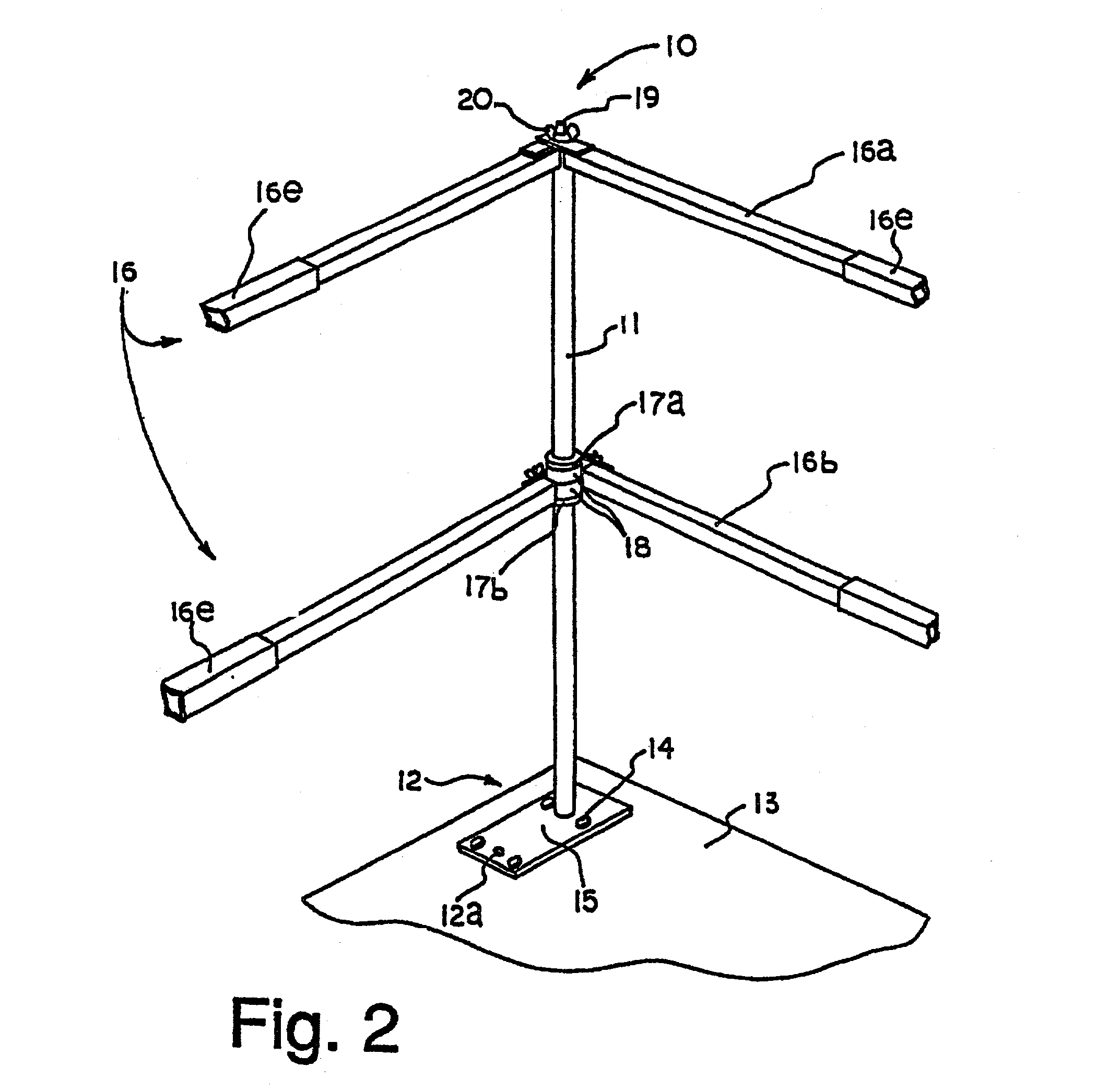
[0040] With further reference to the drawings, the temporary guard rail system in accordance with the present invention is illustrated in FIG. 2 and indicated generally at 10. The temporary guard rail system 10 comprises a plurality of upright stanchions 11 as shown in FIG. 1. In the preferred embodiment, stanchions 11 are formed from solid steel bars in order to comply with OSHA strength regulations. However, it will be appreciated that other materials such as aluminum, fiberglass and similar composites may be utilized in alternative embodiments.

[0041] The lower end of each stanchion 11 has integrally formed therewith or otherwise fixed thereto an anchor bracket, indicated generally at 12, for attaching each stanchion 11 to the building subfloor 13 or other suitable forming members (not shown). In the preferred embodiment, stanchion 11 is positioned in a predetermined location on anchor bracket 12 and is attached in perpendicular relation thereto by weldment or other suitable means...


PUM


Abstract

An improved temporary guard rail system for use by residential and commercial builders on construction sites in those areas of building structures where an accidental fall may result in serious bodily injury. In particular, the temporary guard rail system of the present invention includes a plurality of upright stanchions having mounting brackets integrally formed or attached thereto that are connected by a plurality of vertically spaced, generally horizontal side rails extending end to end. The vertically spaced side rails are adapted for 360 degree rotational movement in both horizontal and vertical planes. In addition, the tubular guard rails are fabricated in a plurality of sections that may be slideably engaged, one inside another, to provide a telescoping adjustment of length. The temporary guard rail system may be adapted and secured to various features of a building such as balconies, elevated platforms, stair cases, and the perimeter of a floor prior to the external walls or permanent protective railings being erected to prevent accidental injury. Further, the temporary guard rail system is designed and manufactured to conform to OSHA requirements for temporary guard rails. This system also provides a versatile safety device which is easy to install, easy to dismantle, and relatively inexpensive to manufacture.

Description

[0001] This application is a Continuation-In-Part application of U.S. application Ser. No. 08 / 421,858 filed Apr. 14, 1995 by Harrison G. Purvis and Tony R. Matthews entitled Temporary Guard Rail System and Method of Using the Same now U.S. Pat. No. 5,683,074.[0002] This invention relates to safety devices and more particularly to temporary guard rails used during construction of buildings.BACKGROUND OF INVENTION[0003] During the construction of buildings, both commercial and residential, there has been a problem in providing safety rails prior to permanent railings being installed on decks, balconies, and even elevated floors prior to the construction of exterior walls.[0004] Quite often, 2.times.4 lumber has been temporarily nailed to form makeshift railings. Structures of this type, however, are usually not strong in structure and a worker or other person falling thereagainst can easily dislodge the makeshift railing causing such person to fall. This of course can result in grievo...

Claims


Application Information

Patent Timeline
IPC IPC(8): E04G21/32E04H17/00E04H17/14
CPCE04G21/3223E04H17/1413E04H2017/006E04H2017/1452E04H2017/1473E04H2017/1491E04H17/006E04H17/1448E04H17/1452E04H17/1473
Inventor PURVIS, HARRISON G.
Owner PURVIS HARRISON G
Learn More