Transmitting/receiving system and transmitting/receiving apparatus
a technology of transmitting/receiving apparatus and transmitting/receiving system, which is applied in the direction of error prevention, digital transmission, link quality based transmission modification, etc., can solve the problems of deteriorating receiving quality, difficult to correctly decode transmitted data, and errors in selectively synthesized receiving data, so as to reduce the deterioration of receiving quality and high quality communication
- Summary
- Abstract
- Description
- Claims
- Application Information
AI Technical Summary
Benefits of technology
Problems solved by technology
Method used
Image
Examples
embodiment 4
[0102] (Embodiment 4)
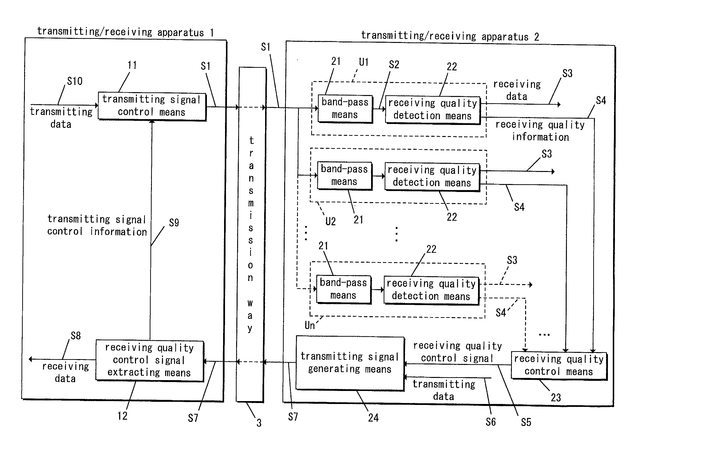
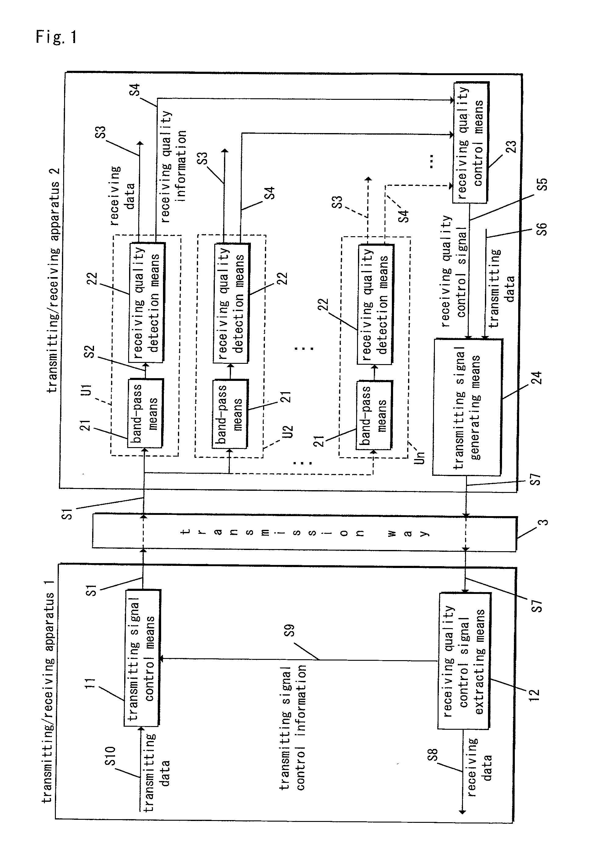
[0103] Referring now to FIG. 6, a transmitting / receiving system according to Embodiment 4 of the invention employs a receiving quality control means 23 similar to the transmitting / receiving system of FIG. 1. That is, the receiving quality control means 23 of Embodiment 4 includes an electric energy amount information generating means 28.
[0104] In addition, in the transmitting / receiving system of FIG. 6, in place of the receiving quality control signal extracting means 12 of the transmitting / receiving system of FIG. 1, contains the amount of electric energy information extracting means 14. In addition, a transmitting signal control information generating means 15 is added. Other elements of construction are the same as those of the transmitting / receiving system of FIG. 1.
[0105] In operation, the electric energy amount information generating means 28 generates, based on the receiving quality information S4 from the plurality of receiving quality detection means 22...
embodiment 5
[0119] (Embodiment 5)
[0120] Referring now to FIG. 7, a transmitting / receiving system includes a receiving quality control means 23 similar to the transmitting / receiving system of FIG. 1. That is, the receiving quality control means 23 includes an error rate of receiving data-measuring means 29. The transmitting / receiving system of FIG. 7 substitutes an error rate of receiving data-extracting means 16 for the receiving quality control signal extracting means 12 of the transmitting / receiving system of FIG. 1. A transmitting signal control information generating means 15 is added. Other elements of construction are the same as those of the transmitting / receiving system of FIG. 1.
[0121] In operation, the error rate of receiving data-measuring means 29 measures, based on the receiving quality information S4 from the plurality of receiving quality detection means 22, an error rate of receiving data S15 for an output to the transmitting signal generating mean S24. That is, the error rate o...
embodiment 6
[0133] (Embodiment 6)
[0134] Referring now to FIG. 8, a transmitting / receiving system according to Embodiment 6 of the invention is similar to that of FIG. 1, except that the present embodiment includes a number of error bits in receiving-measuring means 30. Also, instead of the receiving quality control signal extracting means 12 of the transmitting / receiving system of FIG. 1, a number of error bits in receiving-extracting means 17 is provided. Furthermore, a transmitting signal control information generating means 15 is added. Other elements of construction are the same as those of the transmitting / receiving system of FIG. 1.
[0135] In operation, the number of error bits in receiving-measuring means 30 measures, based on the receiving quality information S4 from the plurality of receiving quality detection means 22, the number of error bits in receiving S16 for each band. This information is output to the transmitting signal generating means 24. The number of error bits in receiving...
PUM
 Abstract
Description
Claims
Application Information
 - R&D
- Intellectual Property
- Life Sciences
- Materials
- Tech Scout
- Unparalleled Data Quality
- Higher Quality Content
- 60% Fewer Hallucinations
Browse by: Latest US Patents, China's latest patents, Technical Efficacy Thesaurus, Application Domain, Technology Topic, Popular Technical Reports.
© 2025 PatSnap. All rights reserved.Legal|Privacy policy|Modern Slavery Act Transparency Statement|Sitemap|About US| Contact US: help@patsnap.com


