
Method and system for exchange of multicall capabilities between terminal and network

Inactive Publication Date: 2001-10-04
TELEFON AB LM ERICSSON (PUBL)
View PDF4 Cites 46 Cited by
  • Summary
  • Abstract
  • Description
  • Claims
  • Application Information

AI Technical Summary

Benefits of technology

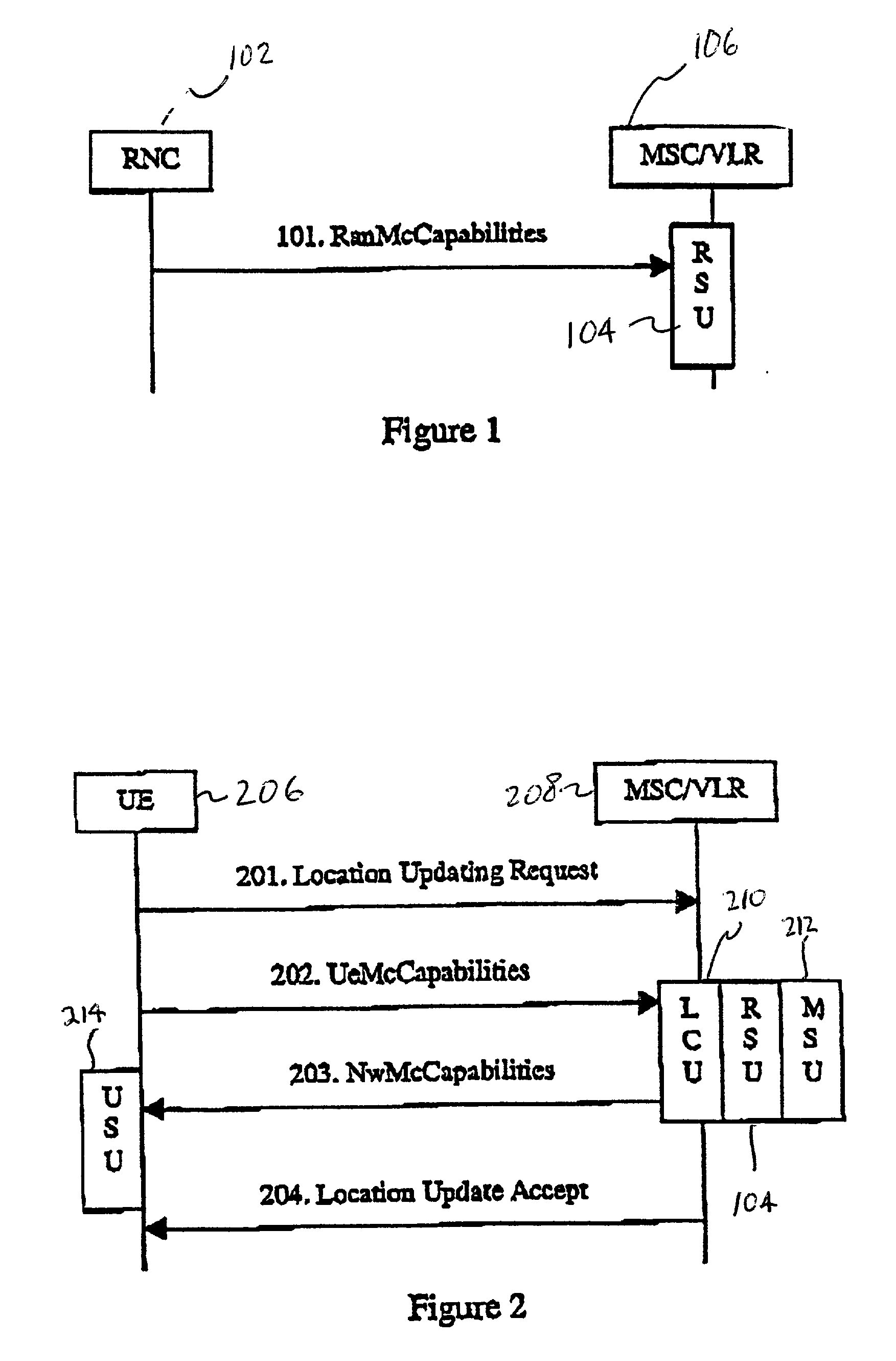
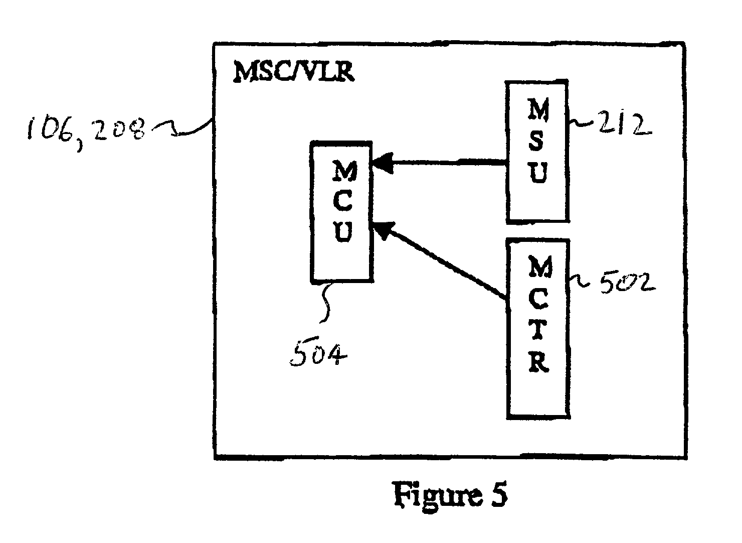
[0023] According to one exemplary embodiment of the present invention the involved entities provide a limit calculation unit with their bearer limit information. This limit calculation unit determines the actual limit on the number of available bearers for a given set of entities at a given time. This actual limit can then be returned to the involved entities and used to invoke multicall capabilities in a manner which prevents the afore-described problems.

Problems solved by technology

In addition to the MSC / VLR mentioned above, the capabilities of the serving network in connection with the number of bearers available may also be limited by other nodes, e.g, the Radio Network Controller (RNC).
However, currently no mechanism exists to detect the actual limit for the number of bearers available to a Multicall subscriber.
This can cause a number of problems in the handling of calls made by GSM and / or UMTS equipment, particularly in hybrid GSM / UMTS equipment.
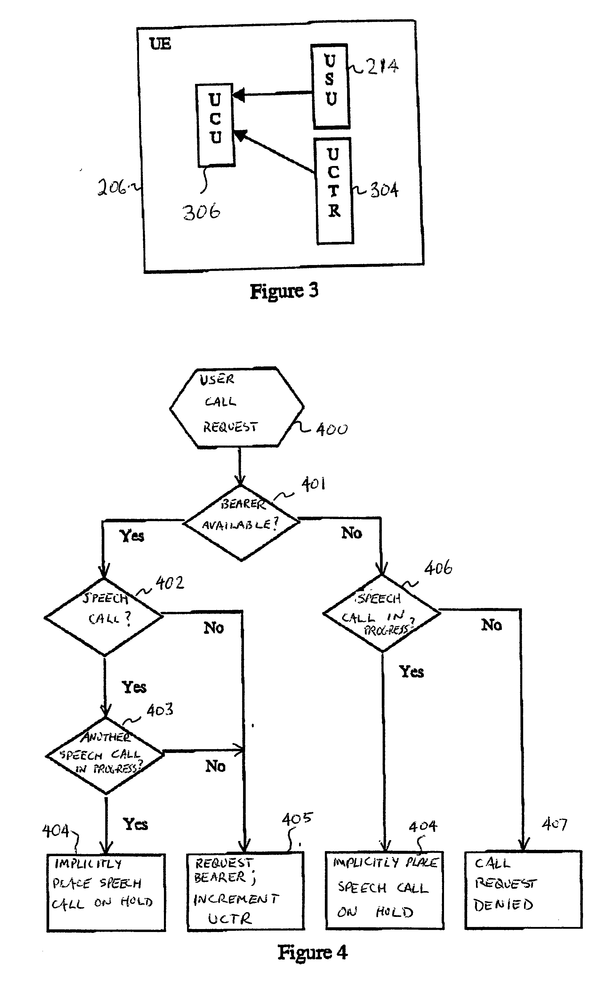
For example, if the maximum number of bearers supported by the terminal is higher than the maximum number of bearers supported by the serving network entity, the following problems can occur.
However, since the maximum number of bearers from the terminal point of view is not yet reached, it may request the serving network entity to allocate a new bearer for the waiting call, which bearer is not available.
Likewise, for calls which are to be setup from the terminal, this imbalance between the number of bearers available for the terminal versus the number of bearers available for the serving network entity can cause difficulties.
Problems may also occur for the reverse discrepancy, i.e., in the case that the maximum number of bearers supported by the terminal is lower than the number of bearers that can be offered by the network.

Method used


Image

  • Method and system for exchange of multicall capabilities between terminal and network
  • Method and system for exchange of multicall capabilities between terminal and network
  • Method and system for exchange of multicall capabilities between terminal and network

Examples


Embodiment Construction

[0035] The various features of the invention will now be described with reference to the figures, in which like parts are identified with the same reference characters. In the following description, for purposes of explanation and not limitation, specific details are set forth, such as particular circuits, circuit components, techniques, etc. in order to provide a thorough understanding of the present invention. However, it will be apparent to one skilled in the art that the present invention may be practiced in other embodiments that depart from these specific details. In other instances, detailed descriptions of well-known methods, devices, and circuits are omitted so as not to obscure the description of the present invention.

[0036] Operation in accordance with GSM communication systems is described in, for example, European Telecommunication Standard Institute (ETSI) documents ETS 300 573, ETS 300 574 and ETS 300 578, which are hereby incorporated by reference. Therefore, the ope...


PUM


Abstract

A communication system supports multicall capabilities. Described herein are methods and techniques for exchanging the multicall capabilities of different entities, e.g., RNCs, MSCs, and terminals, such that the handling of call requests is efficient and backwardly compatible. Multicall capabilities of different entities is forwarded to a limit calculation device. The limit calculation device determines a bearer limit for a set of entities, which limit it transmitted back to at least some of the entities which forwarded their capability information. The bearer limit is used to selectively setup subsequent calls.

Description

RELATED APPLICATION[0001] This application is related to, and claims priority from, U.S. Provisional Patent Application Ser. No. 60 / 174,908, entitled "Exchange of Multicall Capabilities between UE and CN in UMTS", filed on Jan. 10, 2000, the disclosure of which is incorporated here by reference.BACKGROUND[0002] The present invention relates to handling and signaling associated with multicall capability in radiocommunication systems.[0003] Radiocommunication standards and systems continue to evolve at a fast pace in recent years. The so-called third generation networks are among the latest developments in this sector, one example of which is referred to as the Universal Mobile Telecommunication Systems (UMTS). These third generation networks enable subscribers to set up a variety of different user services, e.g., multimedia services, speech calls, data calls, fax calls, short messages, etc. Among other capabilities, third generation systems allow a subscriber to set up more than one ...

Claims


Application Information

Patent Timeline
IPC IPC(8): H04W8/18H04W28/18
CPCH04W8/18H04W28/18
Inventor BRUSS, JORG
Owner TELEFON AB LM ERICSSON (PUBL)
Learn More