
Method of operating an appliance

Inactive Publication Date: 2001-08-16
KONINKLIJKE PHILIPS ELECTRONICS NV
View PDF2 Cites 17 Cited by
  • Summary
  • Abstract
  • Description
  • Claims
  • Application Information

AI Technical Summary

Benefits of technology

[0005] An embodiment of the method according to the invention is characterized by the method further comprising a step of displaying transition indications for indicating permissible transitions between said operative states, the movement of the state cursor being restricted to proceed in accordance with said permissible transitions. In this way it is achieved that the user cannot erroneously move the state cursor to a state to which there is no permissible transition, thus avoiding unnecessary error messages from the appliance, or avoiding that the appliance does not respond at all. It is further achieved that the user has a comprehensible overview of which functions can be invoked in different situations A permissible transition between states may, for example, be indicated by means of a line or arrow pointing from one state symbol to another state symbol, thus indicating the direction of the permissible transition. Alternatively, a permissible transition may be indicated by state symbols having a common edge or partially overlapping each other. In response to a user command corresponding to a non-permissible direction, the state cursor remains at its current location or moves to a default location or a location which is determined by guessing the user's intention.
[0007] An embodiment of the method according to the invention is characterized by the method further comprising a step of moving the state cursor relative to a state symbol without affecting the current state of the appliance, so as to select a respective state transition related to said state symbol. This embodiment is advantageous if the number of permissible state transitions is higher than the number of moving direction which can be controlled, or if the layout allows multiple transitions in the same direction. For example, if multiple arrows representing state transitions leave a state symbol in an upward direction, the user may select a starting point of the desired transition by, for example, moving left or right, before actually performing the transition. This selection does not affect the state of the appliance, which is visualized by the current state indicator remaining at the same state symbol.
[0011] The invention is particularly suitable for consumer electronic appliance, since it provides an easy to learn and consistent user interface, and thereby provides the user with a comprehensible overview of the appliance's functionality.

Problems solved by technology

The steady increase in complexity of modern home electronic appliances confronts users of such an appliance with the problem of learning its functions, and in which circumstances these functions can be invoked.
As the number of functions grows, the number of buttons tends to increase as well, which severely reduces the usability of the appliance.
This is confusing to the user, especially when he is not yet familiar with the appliance.
Graphical user interfaces for controlling appliances can remedy these problems to a certain extent but cause new problems, such as complicated menu systems or an abundance of graphical information.
A problem of such an approach is that the user has only a very limited view on the appliance's functionality.

Method used


Image

  • Method of operating an appliance
  • Method of operating an appliance
  • Method of operating an appliance

Examples


Embodiment Construction

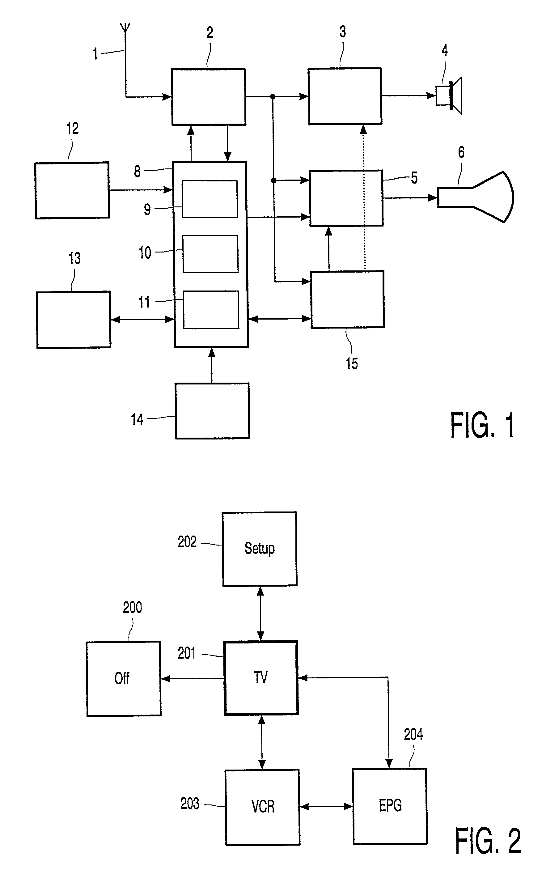
[0017] FIG. 1 shows a diagram of a TV-VCR combination as an embodiment of the appliance according to the invention. TV signals are received from the ether by an antenna 1 or, alternatively, from a cable network. One of the TV signals is selected by a tuner 2 and is decoded and split into an audio signal, a video signal and a data signal. The audio signal is further processed by an audio processor 3 and a loudspeaker 4. The video signal is further processed by a video processor 5 and presented on a screen 6. The data signal is transmitted to a central processing unit (hereinafter "CPU") 8, which comprises one or more microprocessors capable of executing program instructions stored in a read-only memory (hereinafter "ROM") 14. These program instructions comprise parts of software modules including, a user control module 9, an EPG module 10 and a setup module 11. Data processed by said software modules, e.g. EPG data and user profile information, may be stored in a non-volatile memory ...


PUM


Abstract

The invention relates to a method of operating an appliance. The method according to the invention comprises the display of a state diagram on a display screen. The state diagram comprises state symbols representing operative states of the appliance. A state cursor is provided, which indicates a position relative to the state diagram, which state cursor can be relocated in response to user supplied cursor control commands. The appliance can be operated by navigating the state cursor to a state symbol representing a desired state of the appliance, which causes the appliance to adopt the desired state in response to said navigation.

Description

[0001] The invention relates to a method of operating an appliance. The invention further relates to an appliance capable of performing the above method.[0002] The steady increase in complexity of modern home electronic appliances confronts users of such an appliance with the problem of learning its functions, and in which circumstances these functions can be invoked. Traditionally, electronic appliances are controlled by buttons on the appliance itself or on a remote control of the appliance. As the number of functions grows, the number of buttons tends to increase as well, which severely reduces the usability of the appliance. Often, multiple functions are operated by means of a single button, thus requiring, for example, the user to press the button multiple times, account for a time out, or press a `shift` button simultaneously. As a consequence, a button has a different effect in different situations, or has only effect in one situation while being ineffective in another situat...

Claims


Application Information

Patent Timeline
IPC IPC(8): H04N5/445G06F3/00G06F3/0481
CPCH04N5/44513H04N5/44582H04N21/4104H04N21/4316H04N21/47H04N21/488H04N21/4147H04N21/42204H04N21/431H04N21/4312H04N5/445
Inventor THORGEIRSSON, GUDMUND ORN
Owner KONINKLIJKE PHILIPS ELECTRONICS NV
Learn More