
Hybrid vehicle and method of controlling hybrid vehicle

a hybrid vehicle and hybrid technology, applied in the field of hybrid vehicles, can solve the problems of user discomfort, increase in engine speed and motor speed,

Active Publication Date: 2022-10-04
TOYOTA JIDOSHA KK
View PDF6 Cites 0 Cited by
  • Summary
  • Abstract
  • Description
  • Claims
  • Application Information

AI Technical Summary

Benefits of technology

[0004]However, in the above hybrid vehicle, when the engine or the motor outputs torque in a direction in which the engine speed and a motor speed are increased as the clutch is disengaged due to the system stop, the engine speed may increase (race), and a motor speed may increase. A user does not expect an increase in the engine speed and the motor speed when the system is stopped. Therefore, such an increase in the engine speed and the motor speed may make the user feel discomfort.
[0005]A hybrid vehicle and a method of controlling the hybrid vehicle according to the disclosure have an objective to suppress an increase (racing) of the engine speed and an increase of the motor speed when the system is stopped.
[0011]In the aspect above, the electronic control unit may be configured to control the motor such that a difference between a first decrease rate and a second decrease rate is equal to or less than a predetermined difference after the clutch is disengaged. The first decrease rate may be a decrease amount of the engine speed of the engine per unit time, and the second decrease rate may be a decrease amount of the motor speed of the motor per unit time. With this configuration, after the clutch is disengaged, an excessive delay in a decrease of the motor speed, compared to a decrease of the engine speed, can be suppressed. Therefore, it is possible to suppress extension of time from the disengagement of the clutch to the stop of the rotation of the motor.

Problems solved by technology

Therefore, such an increase in the engine speed and the motor speed may make the user feel discomfort.

Method used


Image

  • Hybrid vehicle and method of controlling hybrid vehicle
  • Hybrid vehicle and method of controlling hybrid vehicle
  • Hybrid vehicle and method of controlling hybrid vehicle

Examples


Embodiment Construction

[0020]Next, modes for carrying out the disclosure will be described using an embodiment.

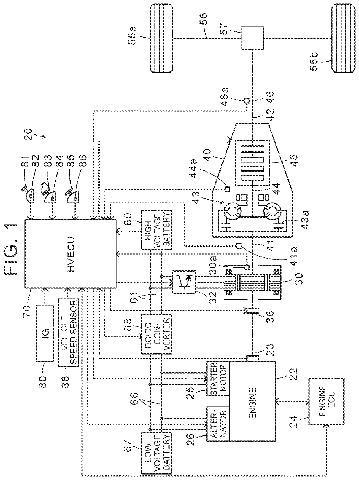
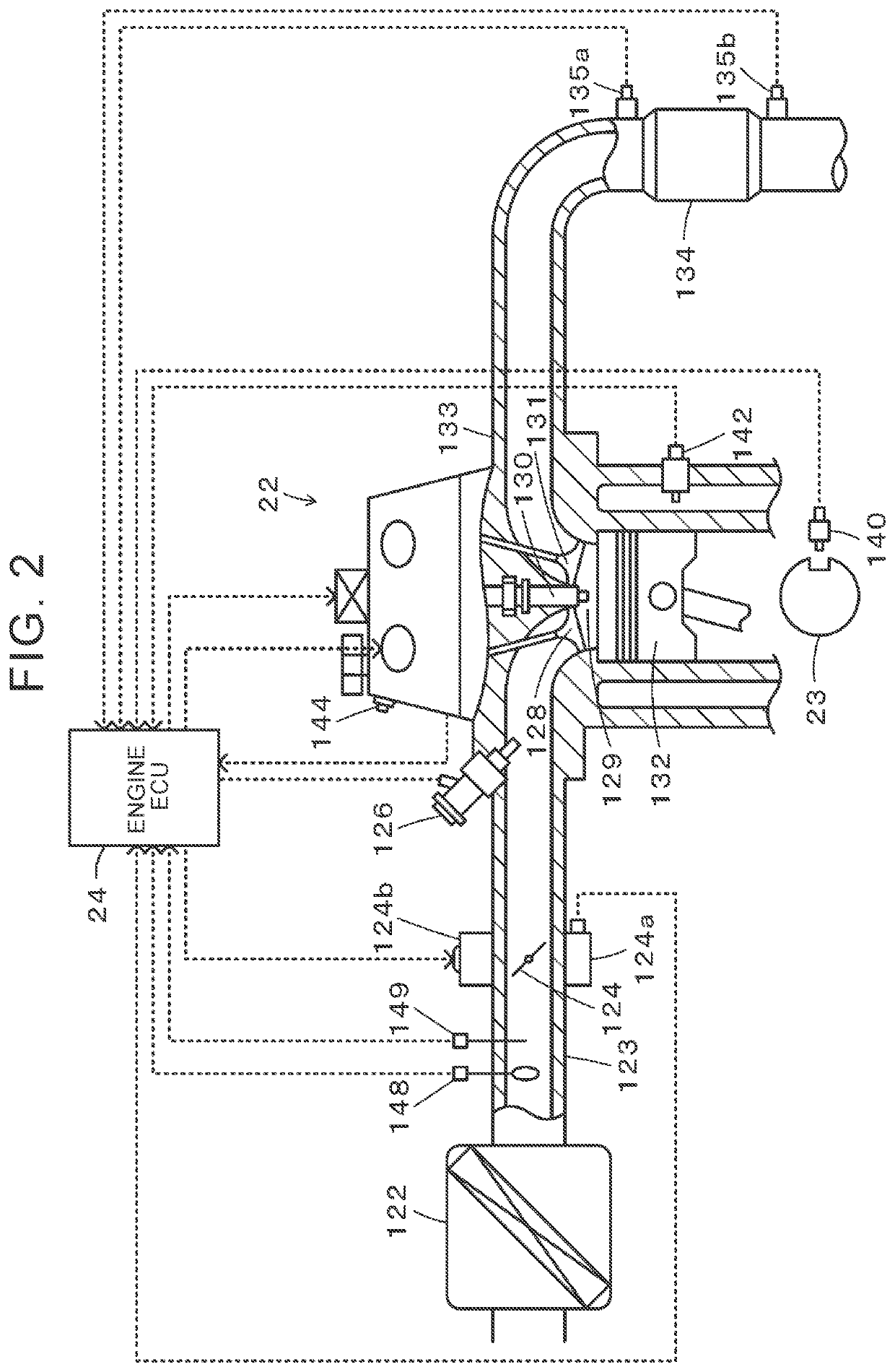
[0021]FIG. 1 is a configuration diagram schematically showing a configuration of a hybrid vehicle 20 as an embodiment of the disclosure, and FIG. 2 is a configuration diagram schematically showing a configuration of an engine 22. As shown in FIG. 1, the hybrid vehicle 20 according to the embodiment includes an engine 22, a motor 30, an inverter 32, a clutch 36, an automatic transmission device 40, a high voltage battery 60, a low voltage battery 67, and a DC / DC converter 68, and a hybrid electronic control unit (hereinafter referred to as “HV ECU”) 70.

[0022]The engine 22 is configured as a four-cylinder internal combustion engine that outputs a power through each stroke of intake, compression, expansion (explosive combustion), and exhaust using gasoline or light oil supplied as fuel from a fuel tank through a fuel supply system. As shown in FIG. 2, the engine 22 takes in an air cleaned by an air ...


PUM


Abstract

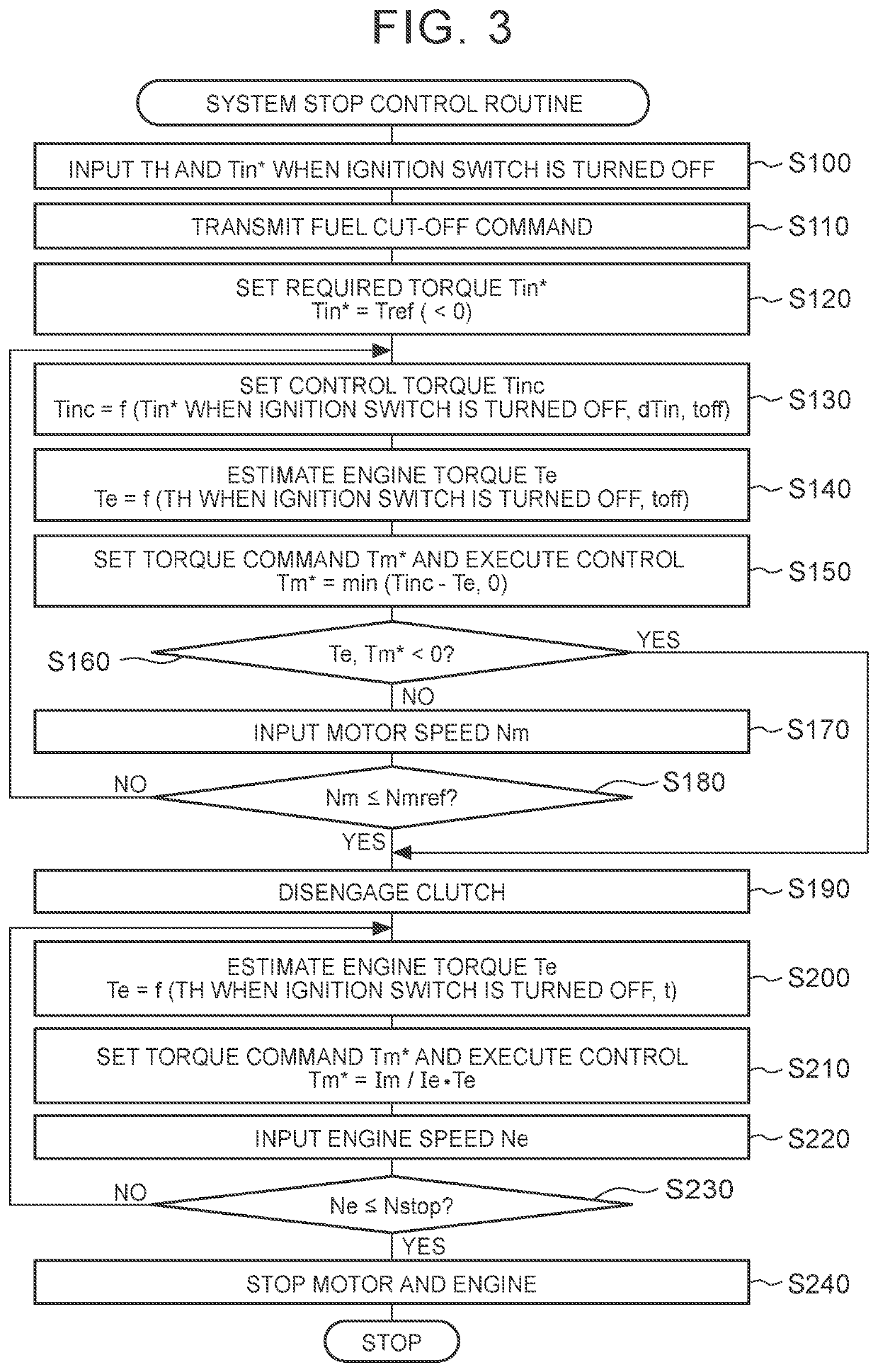
A clutch is disengaged when a torque condition is satisfied at a predetermined time when a system is stopped as a fuel supply to an engine is stopped from a state where the engine is operating with the clutch being engaged. The torque condition is a condition under which torque acting on an output shaft of the engine is torque in a direction in which an engine speed of the engine is decreased and torque output to a rotary shaft of a motor is torque in a direction in which a motor speed of the motor is decreased.

Description

CROSS-REFERENCE TO RELATED APPLICATION[0001]This application claims priority to Japanese Patent Application No. 2020-005093 filed on Jan. 16, 2020, incorporated herein by reference in its entirety.BACKGROUND1. Technical Field[0002]The disclosure relates to a hybrid vehicle and a method of controlling the hybrid vehicle, and more particularly, to a hybrid vehicle including an engine, a motor, and a clutch, and a method of controlling the hybrid vehicle.2. Description of Related Art[0003]In the related art, a hybrid vehicle of this type has been proposed that includes an engine for traveling (internal combustion engine), a motor for traveling (electric motor-generator), and a clutch (refer to, for example, Japanese Patent No. 5949899 (JP 5949899 B)). The clutch connects and disconnects an output shaft of the engine to and from a rotary shaft of the motor. In this hybrid vehicle, when the clutch is normal in the case where a system is stopped while the engine is operating, a fuel suppl...

Claims


Application Information

Patent Timeline
Patent Type & Authority Patents(United States)
IPC IPC(8): B60W10/08B60W20/40B60L15/20B60W10/06
CPCB60W10/08B60L15/2054B60W10/06B60W20/40B60L2240/423B60W10/02B60W30/188B60W30/1884B60W20/10B60L3/0023B60L15/20B60L2240/421B60L2240/441B60L2240/443B60L2240/507B60L50/15B60L50/16B60K2006/4816B60K6/48B60W2710/0666B60W2510/081B60W2510/0208B60W2710/021Y02T10/62Y02T10/64Y02T10/72Y02T10/7072
Inventor WASHIO, TAICHIBABA, MASAYUKIKOBAYASHI, NOBUFUSA
Owner TOYOTA JIDOSHA KK
Learn More