
Hybrid system for controlling an aircraft and method for controlling the same

a hybrid system and aircraft technology, applied in the direction of turbine/propulsion fuel supply systems, charge feed systems, instruments, etc., can solve the problems of high disturbance of the turboprop, unsuitable and unsatisfactory conventional mono-variable architecture and setting strategies

Active Publication Date: 2022-09-06
SN DETUDE & DE CONSTR DE MOTEURS DAVIATION S N E C M A
View PDF13 Cites 0 Cited by
  • Summary
  • Abstract
  • Description
  • Claims
  • Application Information

AI Technical Summary

Benefits of technology

This solution effectively reduces couplings, ensuring robust and efficient engine operation by allowing for easy adjustment and interpolation of control parameters, maintaining optimal performance in terms of response time and overshoot, while simplifying the complexity of control law synthesis and implementation.

Problems solved by technology

Conventional mono-variable architecture and setting strategies are generally not suitable for these systems due to the interactions between the different variables.
The main problem with regulation is that the request for a variation in power SHPref leads to an unwanted variation in the propeller speed of rotation XNP.
These disturbances are highly detrimental to the turboprop.
They lead in particular to significant over-torques which damage the components in fatigue, and particularly the reducer.
Although these solutions are relatively efficient, their development requires significant calculations, and the correctors obtained are generally complex.
Moreover, these control laws are not intuitive, which constitutes an obvious problem for adjusting the settings during engine tests.
Moreover, the state feedback controls are difficult to adjust on the engine test bench.
However, these methods are not compatible with adding integral actions.
Indeed, these methods are based on the movement of a limited number of poles depending on the system, and the fact of adding integrators and therefore unstable poles leads to move them instead of the poles of the system.
The performances obtained are then insufficient, in particular in terms of rejection of disturbances.
Moreover, the state feedback controls are difficult to adjust in practice.
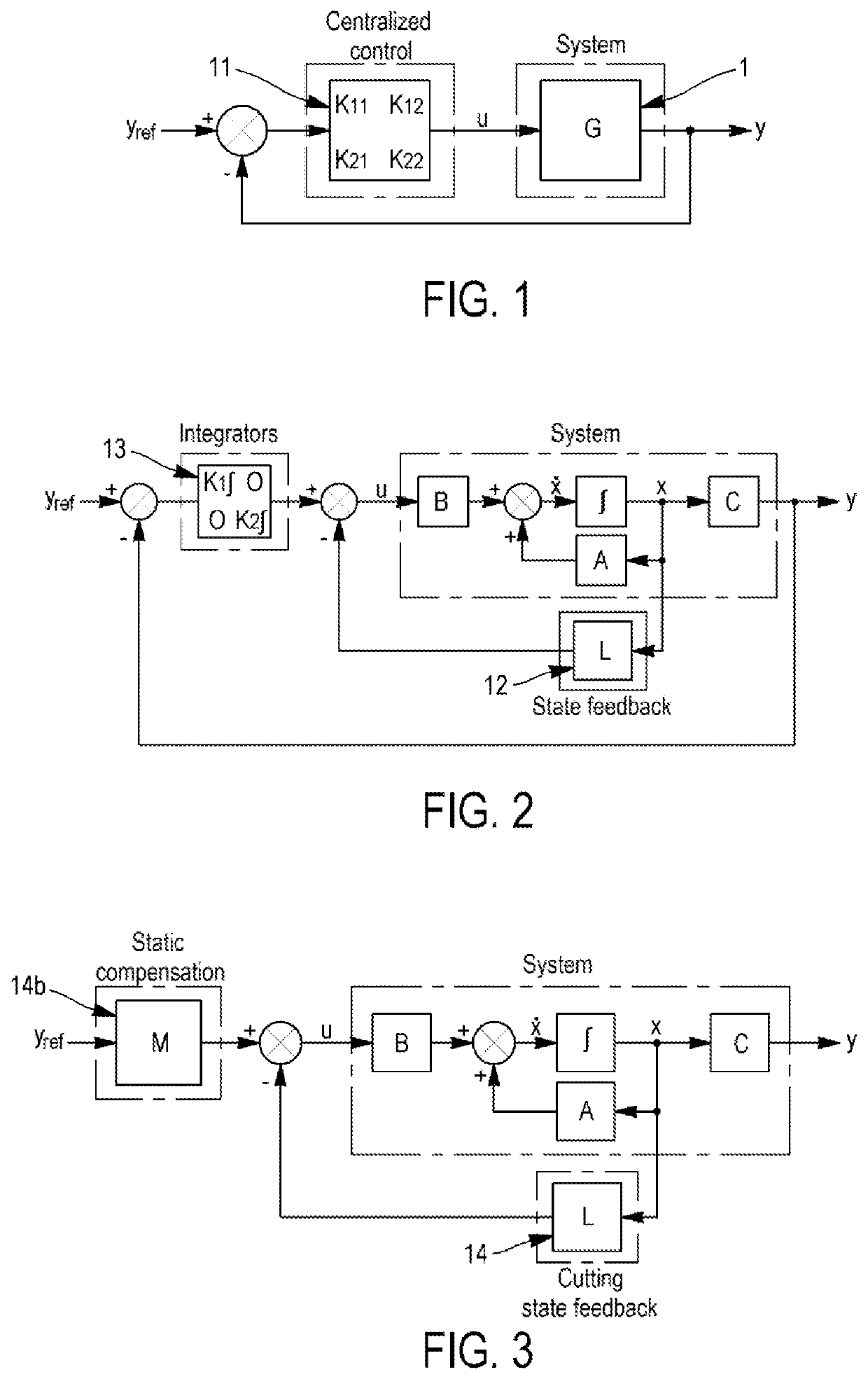
The problem is that simple compensators are generally unable to provide satisfactory decoupling.
A suitable or perfect decoupling can only be achieved by using complex compensators, difficult to implement and interpolate.
The problem with these methods is that the biases are difficult to calculate and not always sufficiently accurate.
This system also does not provide a state feedback control.
As already indicated, these decouplings have the disadvantage of not allowing satisfactory decoupling, except at use of particularly complex compensators.

Method used


Image

  • Hybrid system for controlling an aircraft and method for controlling the same
  • Hybrid system for controlling an aircraft and method for controlling the same
  • Hybrid system for controlling an aircraft and method for controlling the same

Examples


Embodiment Construction

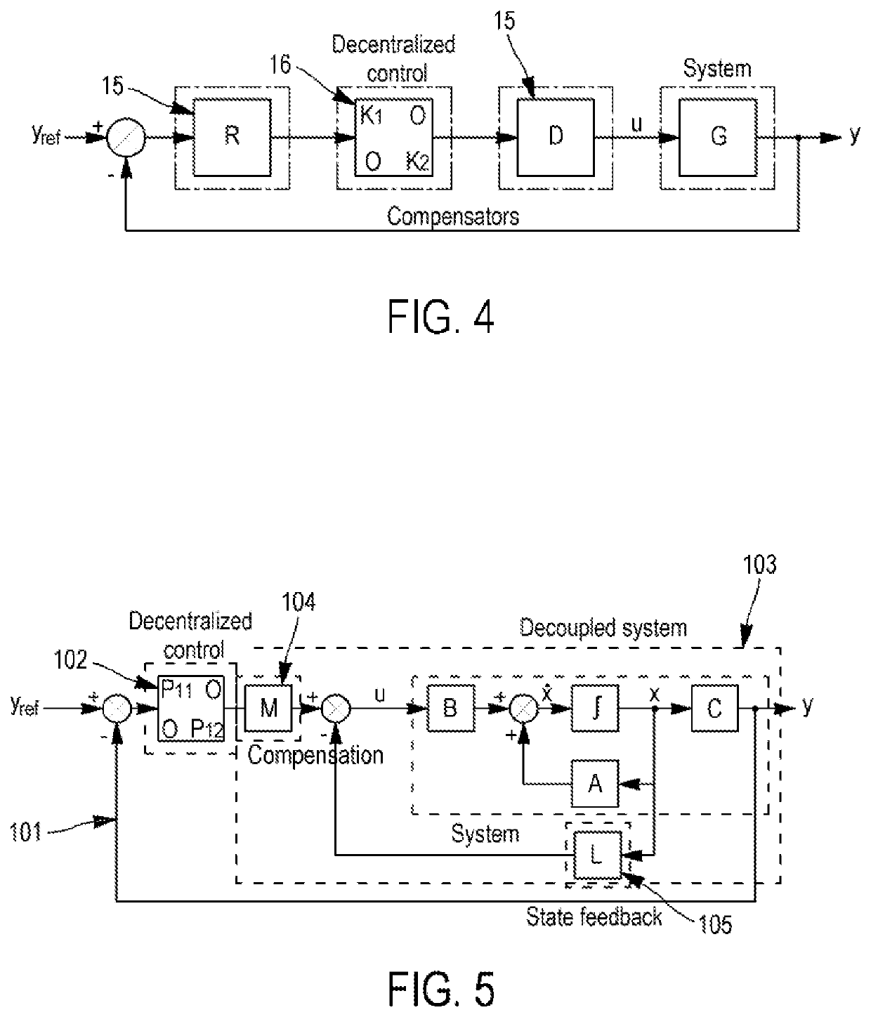
[0094]In the example illustrated in FIG. 5, we are in the case of two setpoints, controls and outputs, this architecture and the setting method being generalized in what follows to N setpoints, controls and outputs.

[0095]The architecture of this control system 100 comprises:[0096]a decentralized control loop 101 with compensators;[0097]a state feedback decoupling system 103 integrated into said loop 101.

[0098]The loop 101 receives N setpoints Yref and comprises a decentralized control 102 the outputs of which supply the state feedback decoupling system 103 and the correctors of which are selected to allow the loop 101 to perform the servo-control function of the method.

[0099]State Feedback Decoupling

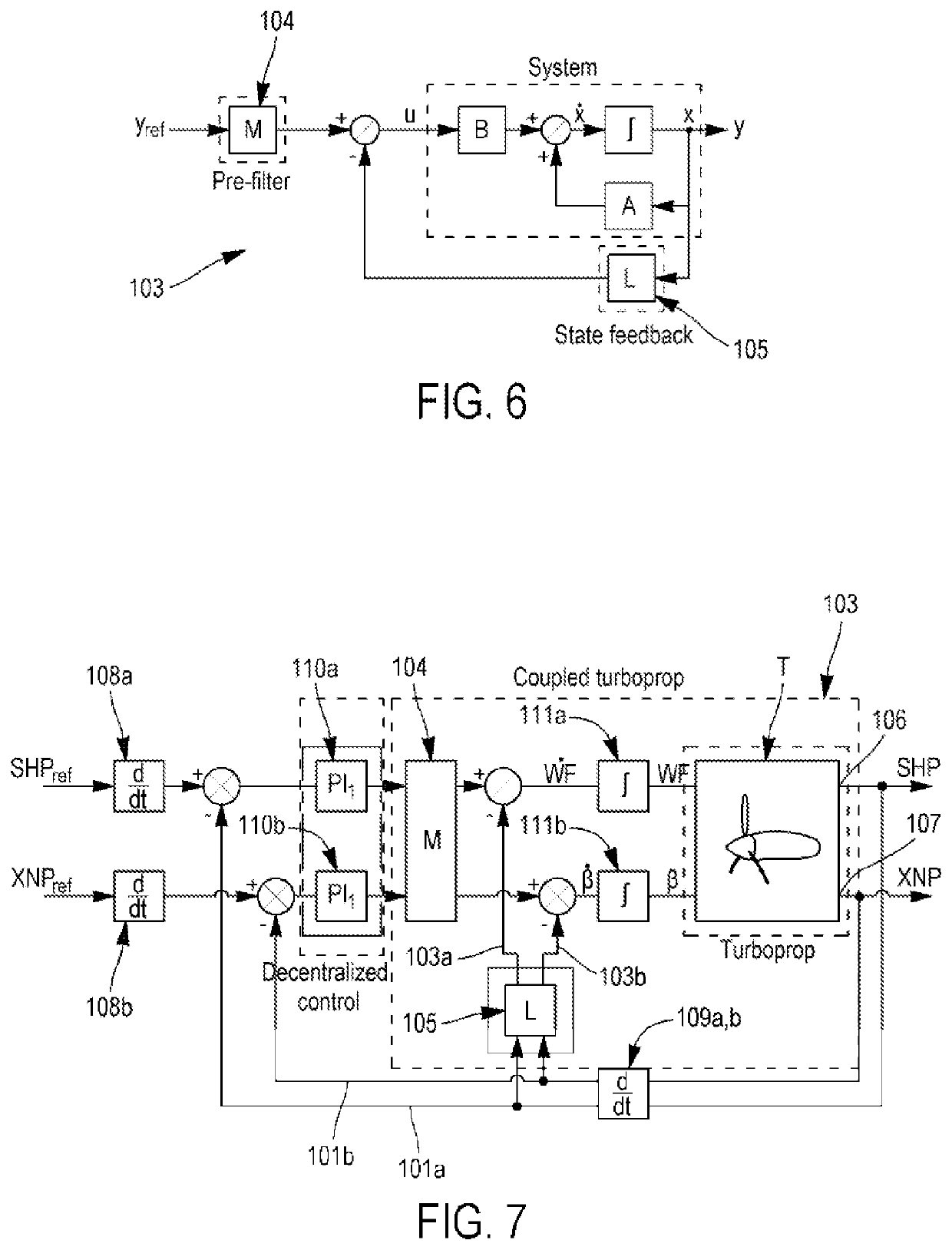
[0100]The state feedback decoupling system is more particularly shown in FIG. 6 and includes:[0101]a static compensator 104 configured to decouple the setpoints at the output of the decentralized control 101 (pre-filter matrix M (or compensation matrix));[0102]a state feedback corrector ...


PUM


Abstract

The proposed aircraft engine control system includes at least one servo-loop, and at least one state feedback control integrated into the servo-loop. The state feedback control includes a static compensator (M) and a state corrector loop (L) which are parametrized so as to decouple the states constituted by the operating parameters of the engine to be servo-controlled. The mono-variable regulators are then in turn parameterized so as to servo-control the operating parameters on the setpoints.

Description

GENERAL TECHNICAL FIELD[0001]In order to optimize the performance of aircraft engines (turbomachines) over the entire flight envelope, one of the possible leverages is to add “variable geometries” (relief valves, vanes or blades with variable pitch, shutters of variable section nozzle, etc.). In a general manner, the variable geometries are members provided with movable elements the position of which can be piloted to vary parameters such as the flowing of a gas flow, and which thus allow having degrees of freedom over the operability of the turbomachine. They are typically piloted by a calculator, and their actions must be coordinated to be optimal in terms of performance and stay within the acceptable limits of operability and operational safety of the turbomachine (in particular in terms of pressure, temperature, speeds of revolution, torques . . . ).[0002]Generally, this is about a multivariable system when a system has several inputs and / or several outputs. Conventional mono-va...

Claims


Application Information

Patent Timeline
Patent Type & Authority Patents(United States)
IPC IPC(8): G05B13/04F02C9/28
CPCG05B13/041F02C9/28G05B11/32Y02T50/60
Inventor LE BRUN, CHRISTOPHE MARC ALEXANDRELIACU, BOGDAN CRISTIAN
Owner SN DETUDE & DE CONSTR DE MOTEURS DAVIATION S N E C M A
Learn More