Vehicle control device and control method for vehicle
a technology for controlling devices and vehicles, applied in the direction of steering parts, automatic steering control, vehicle components, etc., can solve the problems of delayed target travel trajectory correction, uncomfortable feeling, and inability to correct target travel trajectory of the host vehicl
- Summary
- Abstract
- Description
- Claims
- Application Information
AI Technical Summary
Benefits of technology
Problems solved by technology
Method used
Image
Examples
first embodiment
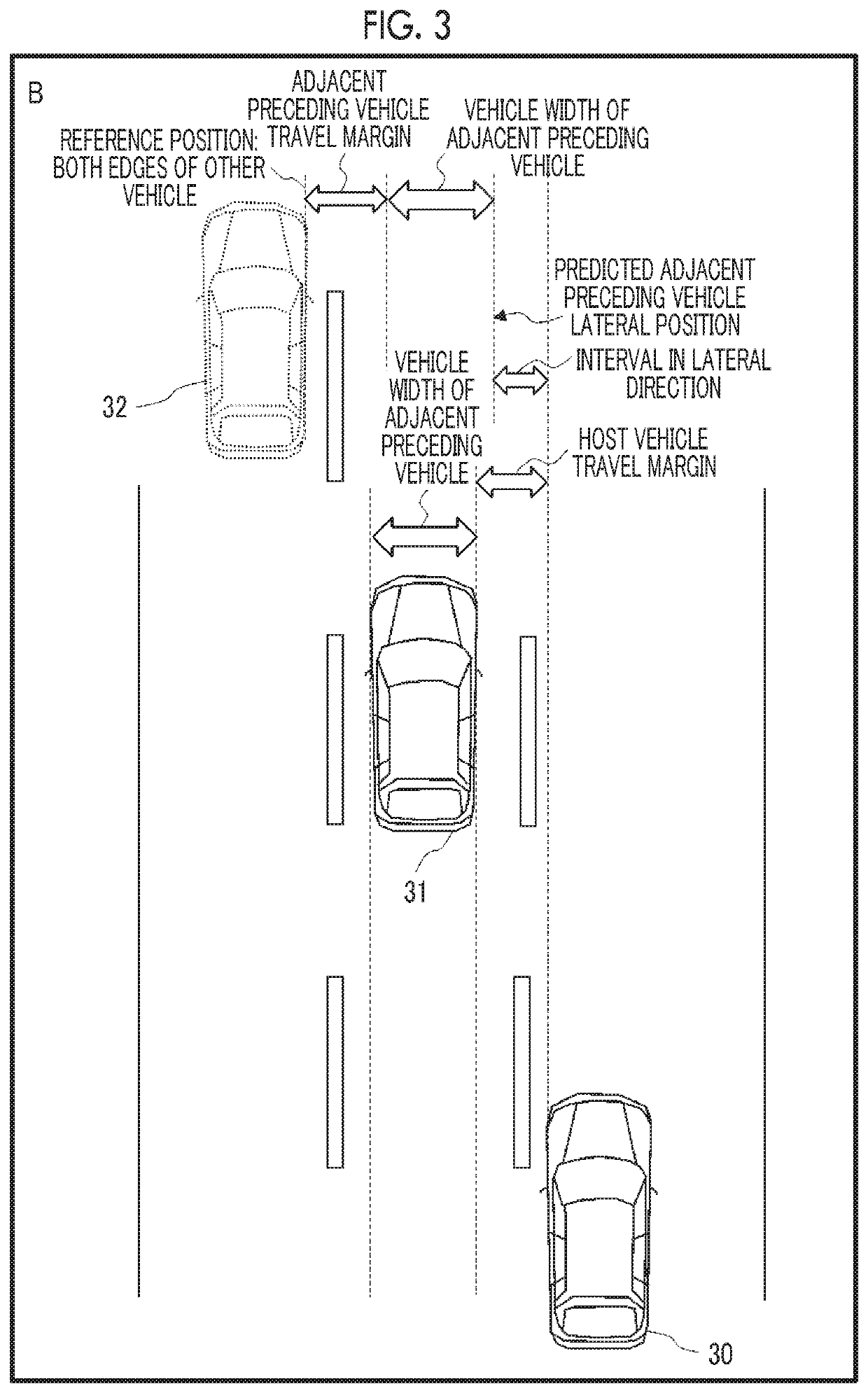
[0025]Constable Host Vehicle Margin & Variable Side-by-side Vehicle Margin
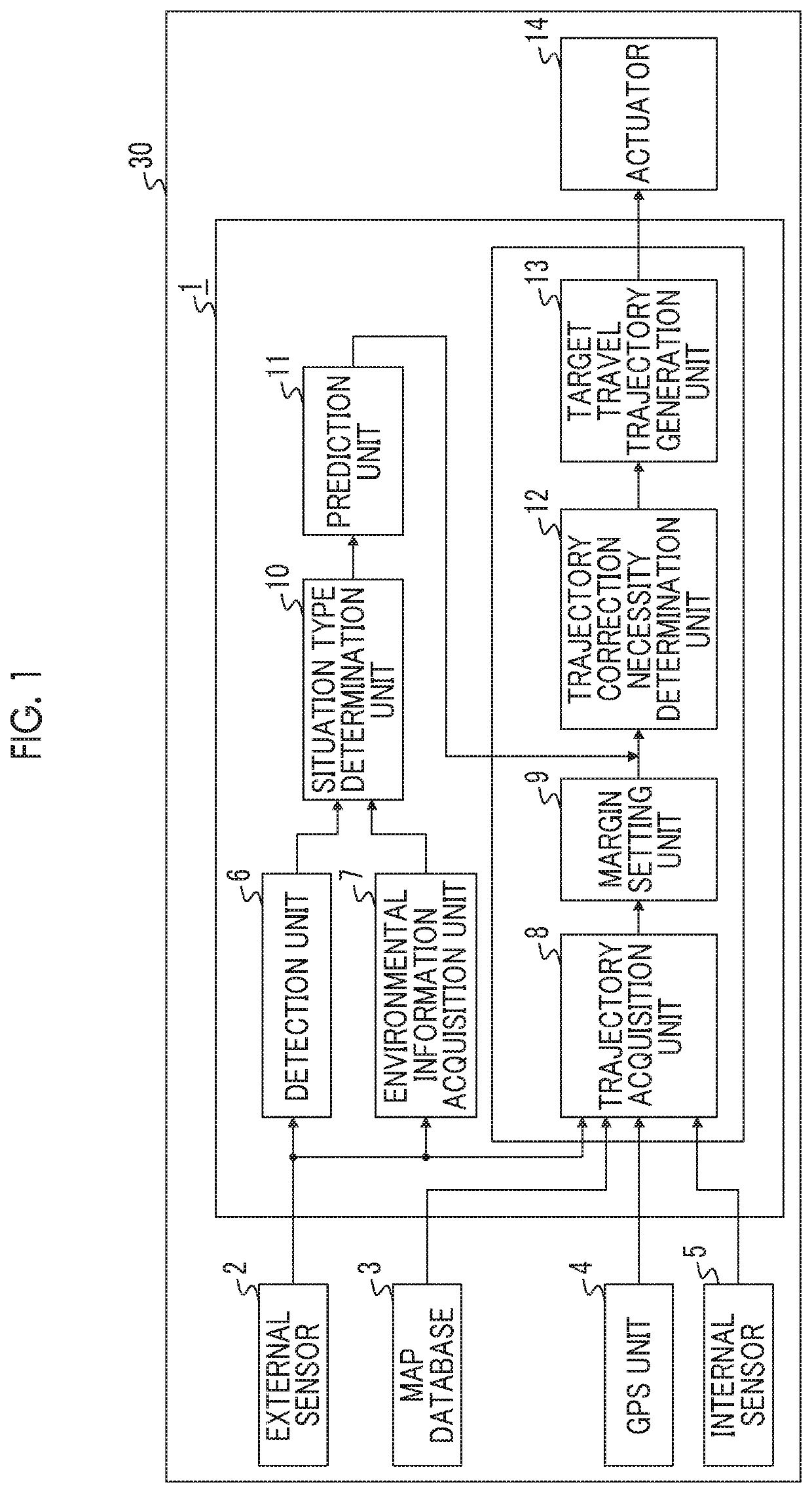
[0026]FIG. 1 is a block diagram illustrating a configuration of a host vehicle 30 in which a vehicle control device 1 of a first embodiment of the present disclosure is installed. The host vehicle 30 is provided with, as shown in FIG. 1, the vehicle control device 1, an external sensor 2 connected to the vehicle control device 1, a map database 3, a GPS unit 4, an internal sensor 5, and an actuator 14. The vehicle control device 1 is provided with a detection unit 6, an environmental information acquisition unit 7, a trajectory acquisition unit 8, a margin setting unit 9, a situation type determination unit 10, a prediction unit 11, a trajectory correction necessity determination unit 12, and a target travel trajectory generation unit 13, as a functional configuration.
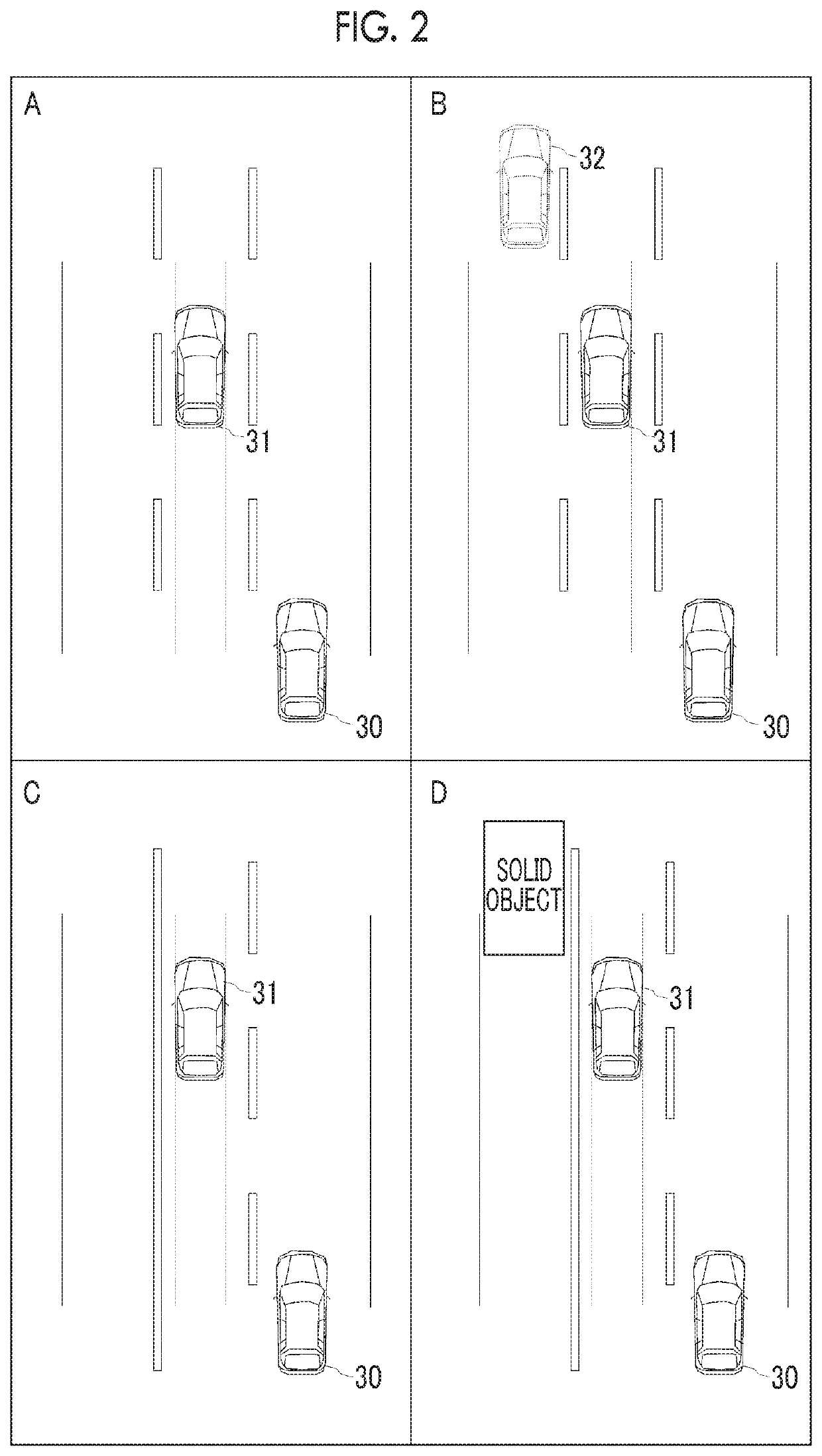
[0027]FIG. 2 shows a bird's-eye view illustrating four situation types including the host vehicle 30, an adjacent preceding vehicle 31 which tra...
second embodiment
[0075]Variable Side-by-Side Zone
[0076]Next, a second embodiment will be described. Hereinafter, distinct features from the first embodiment will be described and repetitive descriptions will be omitted. A difference between the first embodiment and the second embodiment is that, in the second embodiment, the environmental information acquisition unit 7 variably sets a side-by-side zone. The following descriptions explain how to variably set a side-by-side zone by the environmental information acquisition unit 7.
[0077]The environmental information acquisition unit 7 of the second embodiment sets a length of the side-by-side zone in the traveling direction based on the velocity of the adjacent preceding vehicle 31. In the second embodiment, the length of the side-by-side zone in the traveling direction is set by multiplying the velocity of the adjacent preceding vehicle 31 by a specified number of seconds. That is, the length of the side-by-side zone in the traveling direction is a di...
third embodiment
[0080]Variable Adjacent Preceding Vehicle Travel Margin
[0081]Next, a third embodiment will be described. Hereinafter, distinct features from the first embodiment will be described and repetitive descriptions will be omitted. A difference between the first embodiment and the third embodiment is that, in the third embodiment, the prediction unit 11 obtains the predicted adjacent preceding vehicle lateral position based on a variable adjacent preceding vehicle travel margin. The following descriptions explain how to obtain the variable adjacent preceding vehicle travel margin used in the prediction unit 11.
[0082]FIG. 7 is a table illustrating correlations among the situation type shown in FIG. 2, the velocity of the adjacent preceding vehicle 31, which is an adjacent preceding vehicle, and the adjacent preceding vehicle travel margin. As shown in FIG. 7, the adjacent preceding vehicle travel margin proportionally increases as the velocity of the adjacent preceding vehicle increases. A ...
PUM
 Abstract
Description
Claims
Application Information
 - R&D
- Intellectual Property
- Life Sciences
- Materials
- Tech Scout
- Unparalleled Data Quality
- Higher Quality Content
- 60% Fewer Hallucinations
Browse by: Latest US Patents, China's latest patents, Technical Efficacy Thesaurus, Application Domain, Technology Topic, Popular Technical Reports.
© 2025 PatSnap. All rights reserved.Legal|Privacy policy|Modern Slavery Act Transparency Statement|Sitemap|About US| Contact US: help@patsnap.com


