
Adjustment device that controls a tilting angle of a table top

Active Publication Date: 2022-03-29
FOSHAN NANHAI LONGSHENG OFFICE FURNITURE CO LTD
View PDF21 Cites 0 Cited by
  • Summary
  • Abstract
  • Description
  • Claims
  • Application Information

AI Technical Summary

Benefits of technology

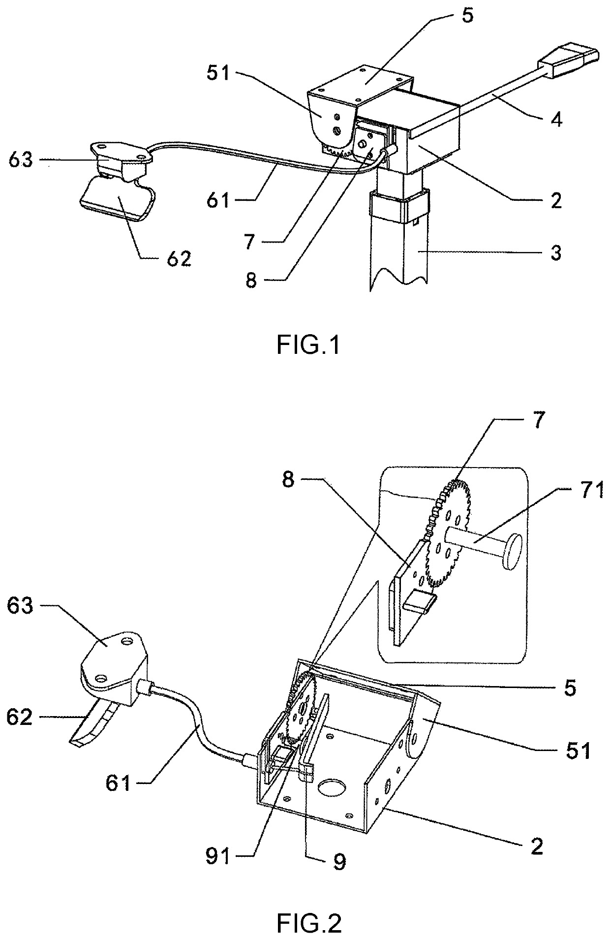
The present invention solves the problems of prior art angle adjustment devices for table tops by providing an easy-to-use and smooth angle adjustment device. The adjustment device controls the tilting angle of the table top and includes a shell, a tilting piece, a gear, a position limiting piece, and a driving piece. The tilting piece is at the front of the shell and rotates about the front edge of the shell, while the gear is at the side of the shell and connected to the tilting piece. The position limiting piece is at the back of the gear and can engage with the gear. The driving piece is inside the shell and is connected to the position limiting piece through a driving rod, which is also connected to the gear. A control string is connected to the driving piece and can be pulled or released to engage or disengage the position limiting piece from the gear. This adjustment device is fast and easy to use, and a string control handle is provided for uniform force application.

Problems solved by technology

A table top of a rostrum is generally fixed and unmovable, in other words, its tilting angle cannot be freely adjusted.
Therefore, the size of the rostrum cannot be changed, and this causes trouble to transportation and carrying.
Also, speakers in need of specific tilting angles of the table top cannot be satisfied.
The angle adjustment device for table top provided by said CN patent is very inconvenient to use.
In case of improper operation, the U-shaped supporting arm 1 that supports the table top fixing seat will fall and hurt the user.
For example, when only one said angle adjustment device is used, the supporting seat 2 and the supporting rod 3 cannot be too long, otherwise the stability of the table top will be poor.
Besides, the number of ratchet teeth on the ratchet tooth racks will affect the fineness of the adjustment.
Moreover, in case two said angle adjustment devices are used symmetrically, installation will become very inconvenient, and the two angle adjustment devices may not be symmetrically installed in case the user is unfamiliar with installation, which may then result in a table top having an uneven plane surface and the problem of non-smooth angle adjustment.

Method used


Image

  • Adjustment device that controls a tilting angle of a table top
  • Adjustment device that controls a tilting angle of a table top

Examples


Embodiment Construction

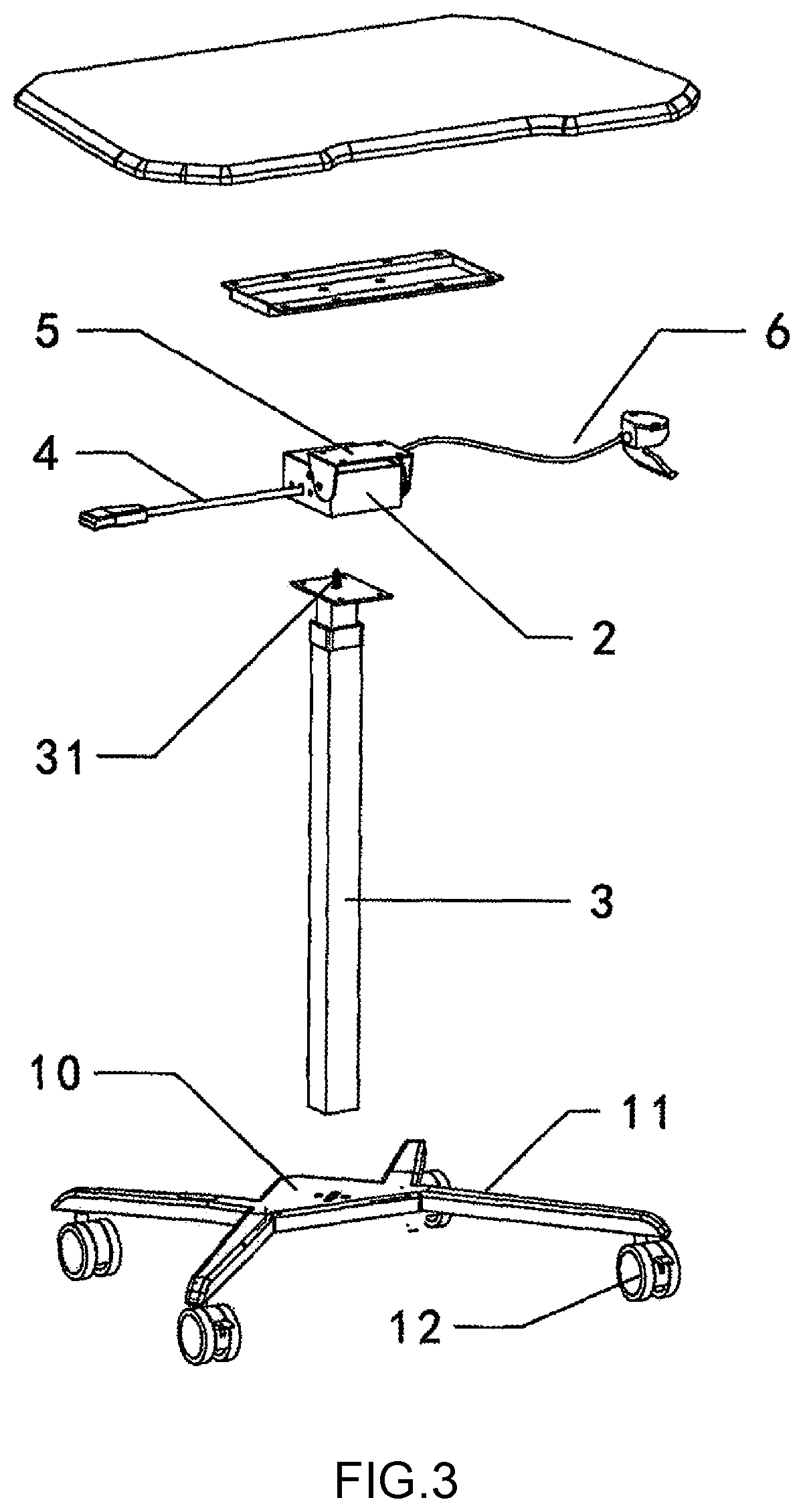
[0014]As shown in FIGS. 1-3, an adjustment device that controls a tilting angle of a table top according to the present invention comprises a shell 2, a tilting piece 5, a gear 7, a position limiting piece 8 and a driving piece 9. The shell 2 is a rectangular box. The tilting piece 5 is adapted to connect with the table top; the tilting piece 5 has a sectional shape of an inverted U-shape. During connection, the tilting piece 5 is connected to the shell, covering a top front portion of the shell 2; a bended portion 51 is provided at each of two sides of the tilting piece 5, and each bended portion is provided with a pin hole through which a pin is inserted to connect the tilting piece with the shell and allows the tilting piece to rotate with respect to the shell. The gear 7 is provided on a left side of the shell 2; the gear 7 is fixedly connected with a corresponding bended portion 51 (one of the two bended portions 51); the tilting piece 5 and the gear 7 are connected with the co...


PUM


Abstract

An adjustment device, having a tilting piece at a top front portion of a shell and rotates about a top front edge of the shell; a gear is at one side of the shell and fixedly connected to one side of the tilting piece, and is rotatable synchronously with the tilting piece; a position limiting piece is provided at a rear side of the gear, and is capable of engaging with the gear; a driving piece is provided in an inclined manner inside the shell; the driving piece and the position limiting piece are connected through a driving rod that passes through an inner side wall of the shell and drives the position limiting piece to move; a far end of the driving piece is connected with one end of a control string; another end of the control string is extended out of the shell to be pulled or released.

Description

BACKGROUND OF THE INVENTION[0001]The present invention relates to the technical field of furniture, and more specifically relates to an adjustment device that controls a tilting angle of a table top.[0002]A table top of a rostrum is generally fixed and unmovable, in other words, its tilting angle cannot be freely adjusted. Therefore, the size of the rostrum cannot be changed, and this causes trouble to transportation and carrying. Also, speakers in need of specific tilting angles of the table top cannot be satisfied.[0003]To solve the problem of non-adjustable tilting angle of a table top, CN201734159U discloses an angle adjustment device for table top. With reference to paragraph 0012 of said CN patent, the angle adjustment device comprises a U-shaped supporting arm 1, a supporting seat 2 and a supporting rod 3; one end of the U-shaped supporting arm 1 rotatably coupled to a table top fixing seat 7; another end of the U-shaped supporting arm 1 is rotatably coupled to a rear end of ...

Claims


Application Information

Patent Timeline
IPC IPC(8): A47B13/08A47B13/02
CPCA47B13/081A47B2013/025A47B2200/0043A47B41/02A47B2200/0021
Inventor GUO, HONGSHENG
Owner FOSHAN NANHAI LONGSHENG OFFICE FURNITURE CO LTD
Learn More