
Robot and robot system comprising same

a robot and robot technology, applied in the field of robots and robot systems, can solve the problems of difficult recognition of flight schedule information, high cost, and limited number of airport robots, and achieve the effects of increasing user convenience, easy boarding of flight-scheduled airplanes, and smooth movement to boarding gates

Active Publication Date: 2022-03-01
LG ELECTRONICS INC
View PDF8 Cites 0 Cited by
  • Summary
  • Abstract
  • Description
  • Claims
  • Application Information

AI Technical Summary

Benefits of technology

The system enhances user convenience by allowing passengers to smoothly reach boarding gates and efficiently manage flight changes, optimizing the use of limited airport robots and improving passenger experience.

Problems solved by technology

However, in high tech devices such as robots, the cost is inevitably high, and due to this, the number of airport robots disposed at airport may be limited.
For example, when flight change information (for example, changed information about a departure time and a boarding gate) about a flight-scheduled airplane occurs, a boarding person of the flight-scheduled airplane may recognize the flight change information transferred through indoor broadcasting at airport, but a problem where it is difficult to recognize flight schedule information may occur actually.

Method used


Image

  • Robot and robot system comprising same
  • Robot and robot system comprising same
  • Robot and robot system comprising same

Examples


first embodiment

[0061]FIG. 4 is a block diagram illustrating a control configuration of an airport robot according to a

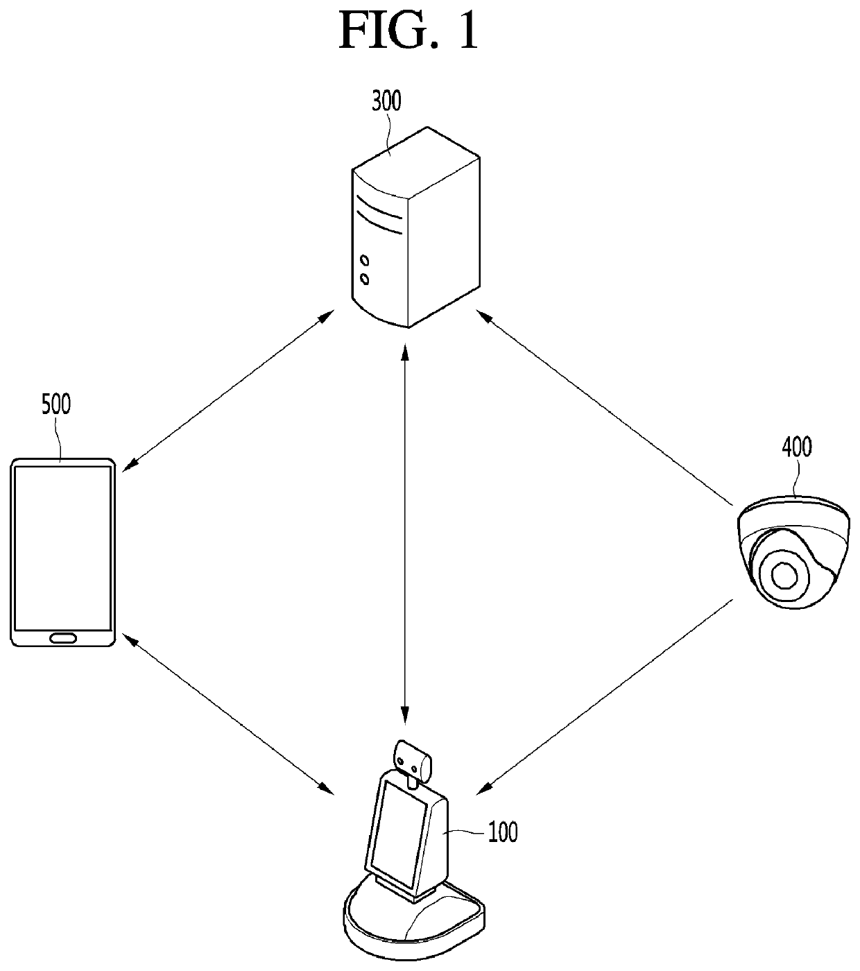
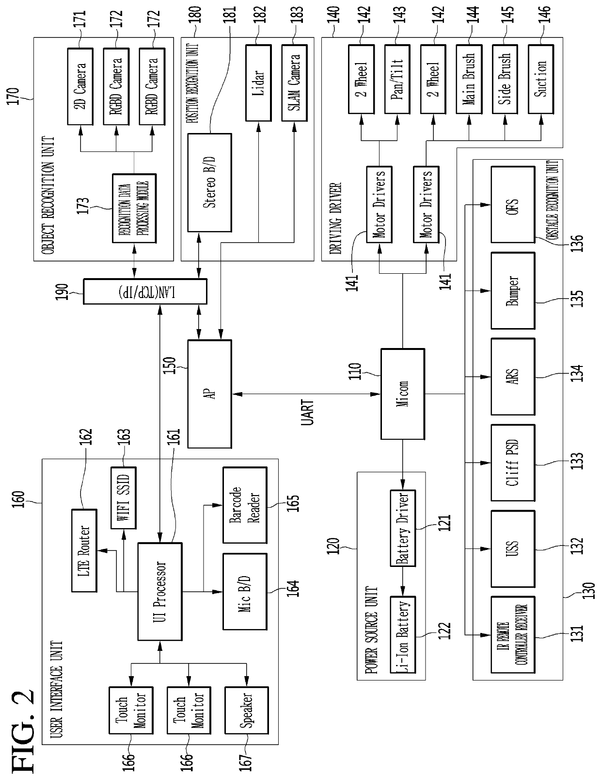
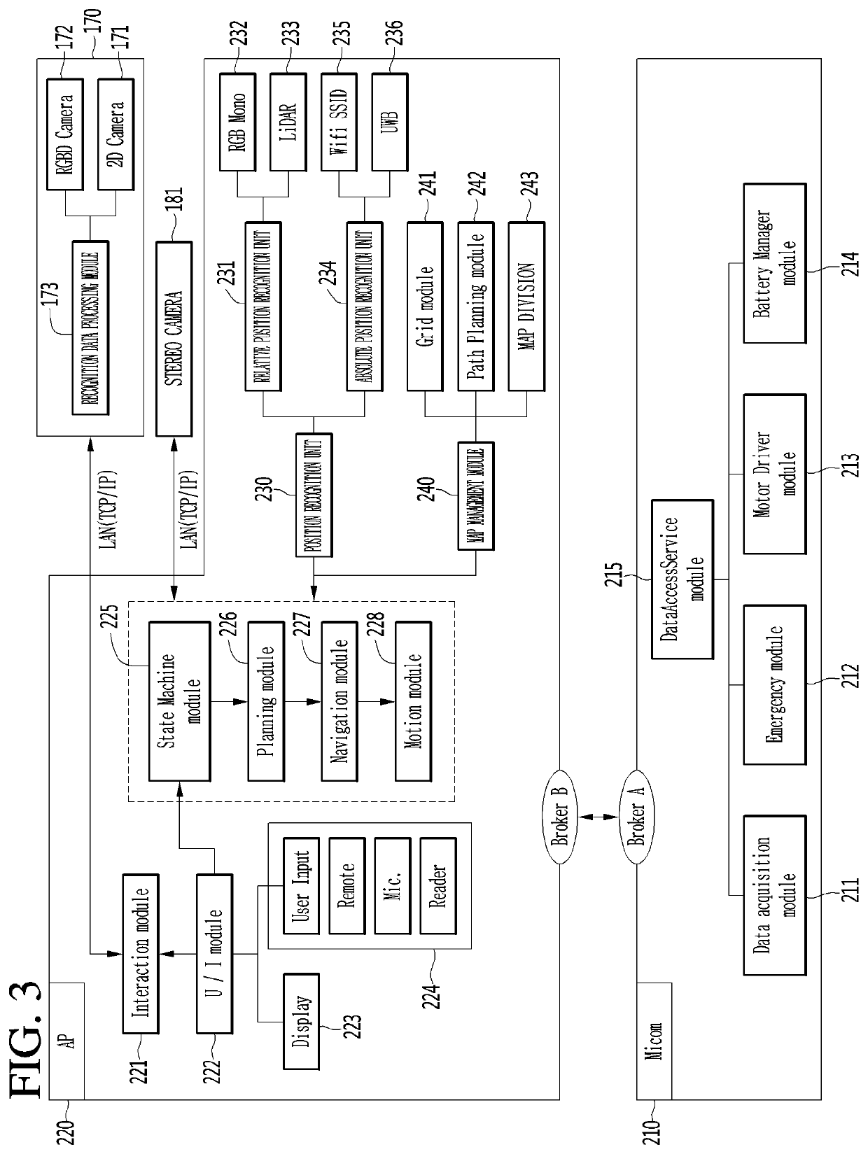
[0062]FIG. 4 illustrates a control configuration needed for a boarding person to recognize flight change information (or ticket change information) about a configuration of the airport robot illustrated in FIGS. 2 and 3. In the control configuration illustrated in FIG. 4 and the configurations illustrated in FIGS. 2 and 3, an element may be added, or the term may be changed.

[0063]Referring to FIG. 4, an airport robot 600 may include a communication unit (or communication interface) 610, an image photographing unit 620, an image recognizer 630, a driving driver 640, an output unit 650, and a controller 660.

[0064]In an embodiment, it will be described that the airport robot 600 is located in another gate region differing from a boarding gate region of a flight-scheduled airplane at a current time, and when a boarding person of the flight-scheduled airplane is located in the other gat...

second embodiment

[0103]FIG. 8 is a block diagram illustrating a control configuration of an airport robot according to a

[0104]Referring to FIG. 8, an airport robot 700 may include a communication unit 710, an image photographing unit 720, an image recognizer 730, a driving driver 740, an output unit 750, and a controller 760.

[0105]In an embodiment, it will be described that the airport robot 700 is located in another gate region differing from a boarding gate region of a flight-scheduled airplane at a current time, and when a boarding person of the flight-scheduled airplane is located in the other gate region, the airport robot 700 provides the boarding person with a service which allows the boarding person to move the boarding gate region of the flight-scheduled airplane.

[0106]Here, the communication unit 710 may receive a facial image fs and a mobile terminal information cs of a ticket-issued person of a flight-scheduled airplane and flight change information vs of the flight-scheduled airplane fr...


PUM


Abstract

An embodiment provides a robot including an image photographing unit configured to photograph image information about boarding-scheduled persons located in a gate region differing from a set boarding gate region of a flight-scheduled airplane, an image recognizer configured to perform image processing on the image information to recognize a boarding person matching a facial image of a ticket-issued person of the flight-scheduled airplane among the boarding-scheduled persons, and a controller configured to, when the boarding person is recognized, output movement path information so that the boarding person moves to the boarding gate region.

Description

CROSS-REFERENCE TO RELATED PATENT APPLICATIONS[0001]This application is a U.S. National Stage Application under 35 U.S.C. § 371 of PCT Application No. PCT / KR2017 / 010445, filed Sep. 22, 2017, which claims priority to Korean Patent Application No. 10-2016-0132631, filed Oct. 13, 2016, whose entire disclosures are hereby incorporated by reference.TECHNICAL FIELD[0002]The present invention relates to a robot and a robot system including the same, and more particularly, a robot and a robot system including the same, which may provide flight change information and flight information about a flight-scheduled airplane.BACKGROUND ART[0003]Recently, introduction of robots and the like is being discussed for more effectively providing various services to users at public places such as airport. Users may use various services such as a road guidance service, a boarding information guidance service, and other multimedia content providing services by using robots disposed at airport.[0004]However,...

Claims


Application Information

Patent Timeline
Patent Type & Authority Patents(United States)
IPC IPC(8): B25J9/00B25J9/16B25J11/00B25J19/02G06K9/00
CPCB25J9/1697B25J9/1664B25J9/1679B25J11/0005B25J11/008B25J19/023G06K9/00261G06Q50/40G06V40/167
Inventor YANG, SUNHO
Owner LG ELECTRONICS INC
Learn More