Crystal oscillator and startup method for a crystal oscillator

a crystal oscillator and startup method technology, applied in the field of crystal oscillators, can solve the problems of affecting the quality or precision of the phase information derived from the comparator, and achieve the effect of improving the quality or precision of the phase information

Active Publication Date: 2022-02-15
THE SWATCH GRP RES & DEVELONMENT LTD
View PDF10 Cites 0 Cited by
  • Summary
  • Abstract
  • Description
  • Claims
  • Application Information

AI Technical Summary

Benefits of technology

[0013]The crystal oscillator further comprises a phase shifting unit coupled to the digital storage and coupled to the output terminal of the comparator. The phase shifting unit is operable to generate or to modify the timing signal on the basis of the comparative signal and on the basis of the digital data provided by the digital storage. In this way the dispersion of the comparator and the impact of the dispersion on the correct determination of the phase of the oscillator structure can be effectively compensated.
[0040]Accordingly and when in the operation mode the digital data is retrieved from the digital storage and the timing signal is generated or modified on the basis of the comparative signal as provided by the comparator of the crystal oscillator and on the basis of the retrieved digital data. In this way and when in the operation mode the impact of comparator dispersion can be effectively compensated for.

Problems solved by technology

Insofar, the quality or precision of the phase information derived from the comparator may be somewhat affected.
It may be even false.

Method used


Image

  • Crystal oscillator and startup method for a crystal oscillator
  • Crystal oscillator and startup method for a crystal oscillator

Examples


Embodiment Construction

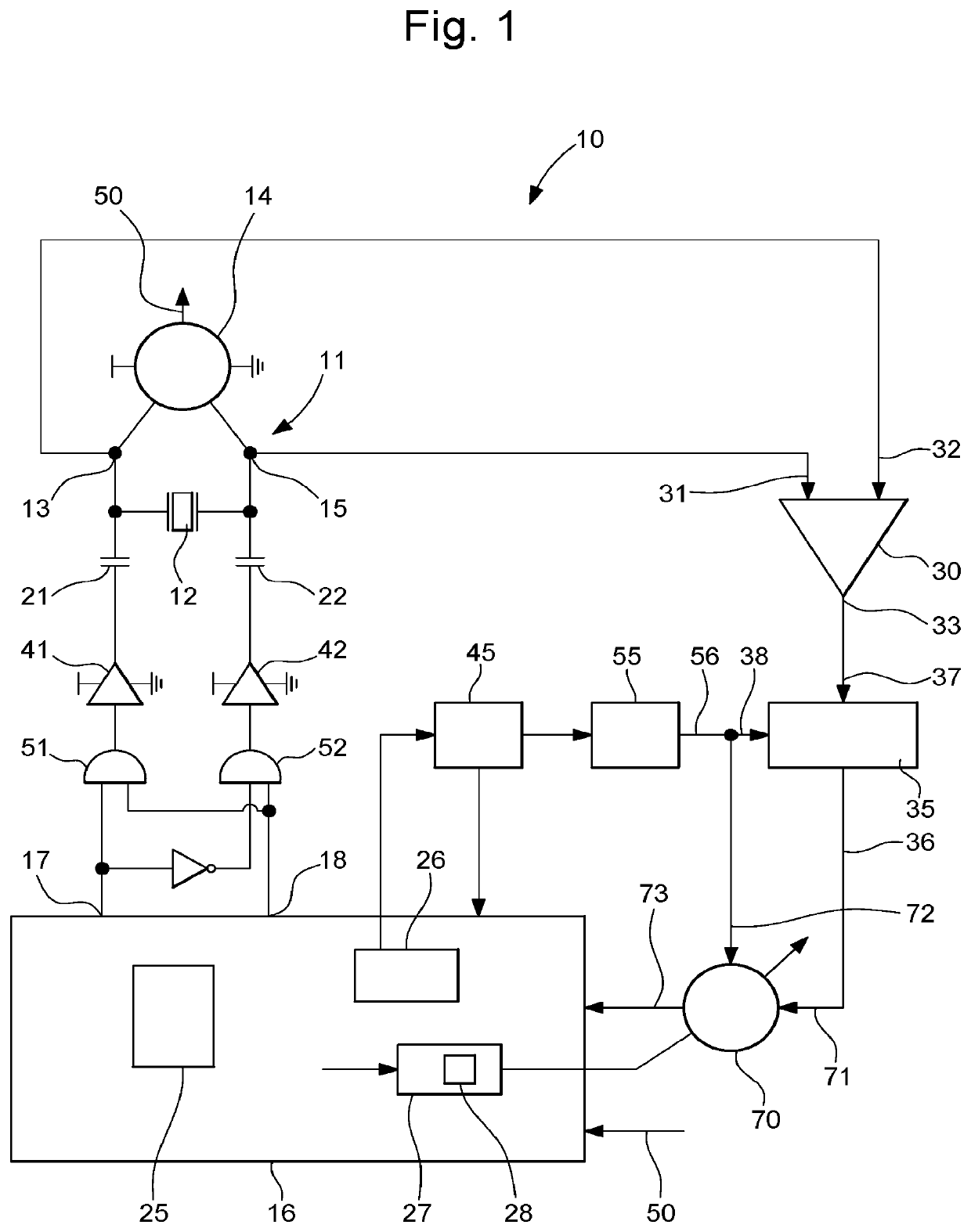
[0047]In FIG. 1 an example of the crystal oscillator 10 is schematically illustrated. The crystal oscillator 10 comprises an oscillator structure 11. The oscillator 11 comprises a crystal resonator 12 and an electronic oscillator circuit 14. The crystal resonator 12 is electrically coupled to the electronic oscillator circuit 14. Typically, the crystal resonator 12 is connected in parallel to the electronic oscillator circuit 14. The oscillator structure 11 comprises a first terminal 13 and a second terminal 15. First and second terminals are connected to respective first and second terminals of the crystal resonator 12 and the electronic oscillator circuit 14. The electronic oscillator circuit 14 comprises an output terminal 50 configured to provide a master clock signal to be used by an electronic device 100, e.g. by a wearable electronic device such as a wristwatch.

[0048]The crystal oscillator 10 further comprises a startup controller 16 configured and operable to conduct a fast ...


PUM


Abstract

A crystal oscillator and a startup method for initiating operation of a crystal oscillator, the crystal oscillator includes an oscillator structure including a crystal resonator and an electronic oscillator circuit connected to the crystal resonator, the oscillator structure having a first terminal and a second terminal, a startup controller operable to initiate an oscillation in the oscillator structure by exciting the oscillator structure with a sequence of excitation signals derivable from a clock signal and when triggered by a timing signal, the sequence of excitation signals includes at least a first excitation signal and a second excitation signal, a comparator including a first and a second input terminal and an output terminal, the first input terminal being connected to the first terminal and wherein the second input terminal is connected to the second terminal.

Description

CROSS-REFERENCE TO RELATED APPLICATION[0001]This application claims priority to European Patent Application No. 20194781.9 filed on Sep. 7, 2020, the entire disclosure of which is hereby incorporated herein by reference.FIELD OF THE INVENTION[0002]The present disclosure relates to a crystal oscillator and to a portable electronic device comprising such a crystal oscillator. In another aspect the disclosure relates to a method of initiating operation of a crystal oscillator.BACKGROUND OF THE INVENTION[0003]Crystal oscillators are widely known in the prior art. A crystal oscillator is an electronic oscillating circuit that uses the mechanical resonance of a vibrating crystal of piezoelectric material to create an electric signal with a precise frequency. This frequency is often used to keep track of time, as in quartz-controlled wristwatches in order to provide a stable clock signal for digital integrated circuits and / or to stabilize frequencies for radio transmitters and receivers.[0...

Claims


Application Information

Patent Timeline
Patent Type & Authority Patents(United States)
IPC IPC(8): H03B5/06H03B5/32H03L3/00
CPCH03B5/323H03B5/06H03B5/32H03L3/00H03B2200/0094H03B5/36
Inventor CASAGRANDE, ARNAUDAREND, JEAN-LUC
Owner THE SWATCH GRP RES & DEVELONMENT LTD
Why Eureka
Try Eureka