Casing structure

a technology of casing and shell, applied in the field of casing structure, can solve the problems of oil leakage, inconvenience in use, and leakage of the isolation layer, and achieve the effect of improving the phenomenon of glue overflow and oil leakag

Active Publication Date: 2021-12-14
PEGATRON
View PDF27 Cites 0 Cited by
  • Summary
  • Abstract
  • Description
  • Claims
  • Application Information

AI Technical Summary

Benefits of technology

[0004]The invention provides a casing structure capable of improving phenomena of glue overflow and oil leakage.
[0015]Base on the above, the casing structure provided by the invention has a design of glue overflow buffer for accommodating a part of the glue layer which is melted or softened or leaking oil, such that the part of the glue layer which is melted or softened or the leaking oil can be prevented from leaking through the gap between the two housings. Thus, the casing structure provided by the invention can achieve the improvement of glue overflow and oil leakage to maintain completeness of the appearance of the casing structure.

Problems solved by technology

However, the isolation layer may be melted or softened after having been squeezed, heated and damped for a long time, and the isolation layer may leak from the aforementioned gap, or an oil leakage may occur to the isolation layer due to the material characteristics.
As a result, the appearance of the electronic device may be influenced, or that may even cause use inconvenience.

Method used


Image

  • Casing structure
  • Casing structure
  • Casing structure

Examples


Embodiment Construction

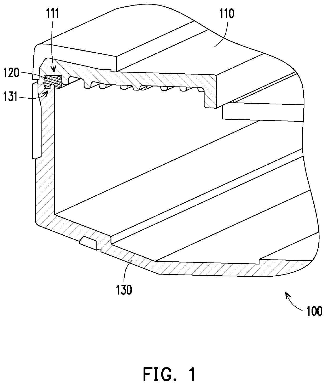
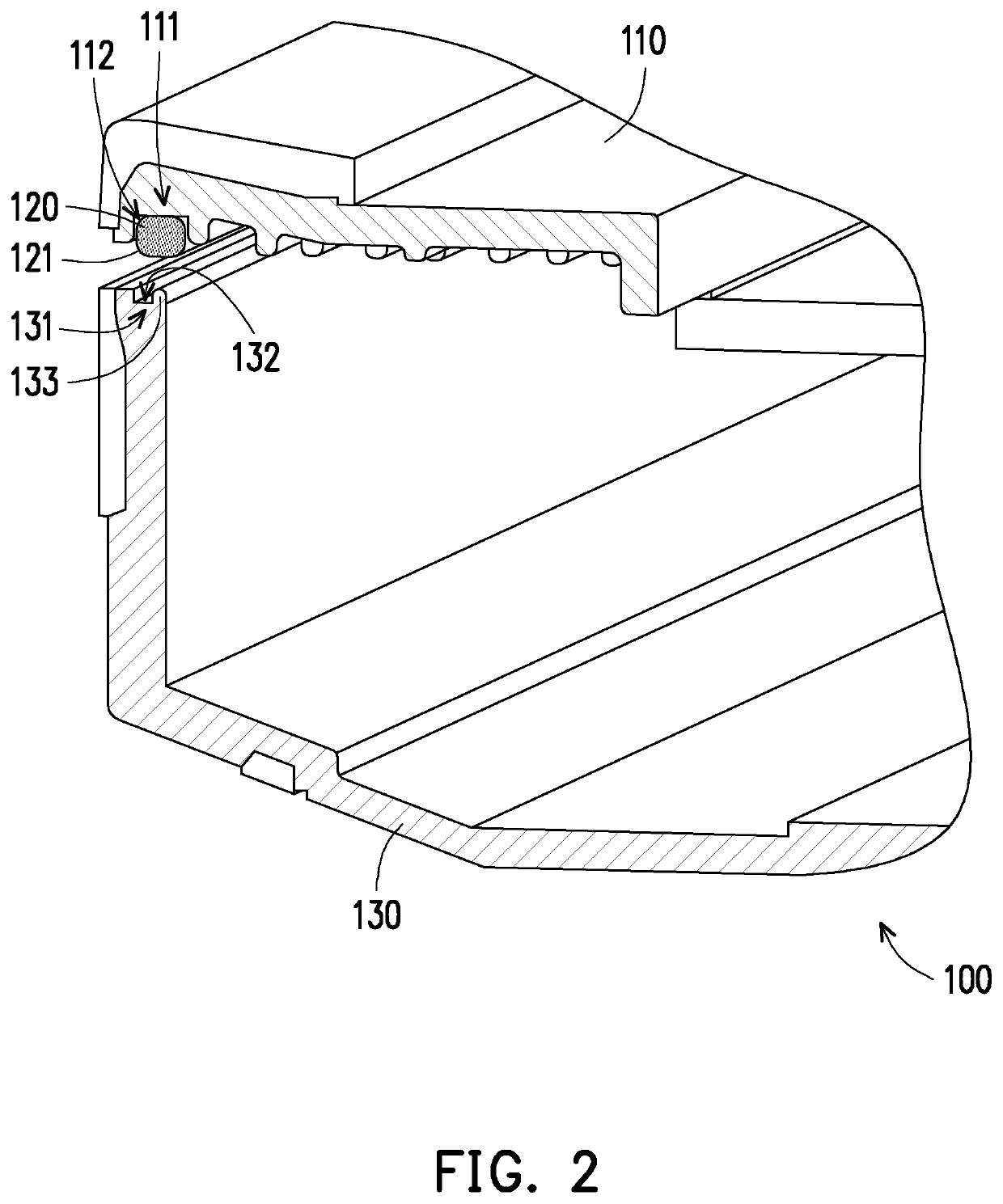
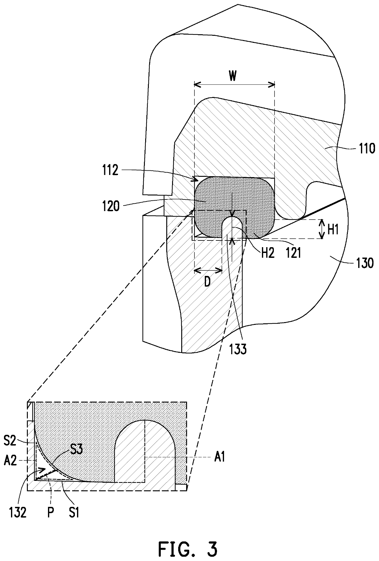
[0021]FIG. 1 is a partially cross-section schematic diagram illustrating a casing structure according to an embodiment of the present invention. FIG. 2 is an exploded schematic diagram illustrating the casing structure depicted in FIG. 1. FIG. 3 is a partially enlarged schematic diagram illustrating the casing structure depicted in FIG. 1. Referring to FIG. 1 to FIG. 3, in the present embodiment, a casing structure 100 may be used by an electronic device, such as a laptop, a tablet computer or a smart phone for protecting electronic components inside the electronic device. The casing structure 100 includes a first housing 110, a glue layer 120, and a second housing 130. Materials of the first housing 110 and the second housing 130 may be metal, plastic, a carbon fiber or a combination of the aforementioned materials, but the materials of the first housing 110 and the second housing 130 are not limited in the invention.

[0022]The first housing 110 and the second housing 130 are assemb...


PUM


Abstract

A casing structure including a first housing, a glue layer, and a second housing is provided. The first housing has a first inner edge. The glue layer is disposed at the first inner edge. The second housing has a second inner edge. The first housing is assembled to the second housing, and the first inner edge is aligned with the second inner edge. The glue layer abuts against the second inner edge so as to combine the first housing with the second housing. A gap formed between the glue layer and a part of the second inner edge is defined as a glue overflow buffer area.

Description

CROSS-REFERENCE TO RELATED APPLICATION[0001]This application claims the priority benefit of Taiwan application serial no. 106218306, filed on Dec. 8, 2017. The entirety of the above-mentioned patent application is hereby incorporated by reference herein and made a part of this specification.BACKGROUNDTechnology Field[0002]The invention relates to a casing structure and more particularly, to a casing structure applied to an electronic device.Description of Related Art[0003]Electronic components inside a commonly seen electronic device, for example, a notebook computer, a tablet computer or smart cell phone, are usually protected by a casing. The casing may be generally separated into two housings assembled to each other, though there might be a gap remaining in between after the two housings are assembled. In order to prevent moisture, dust or external particles from entering into the electronic device through the aforementioned gap, a common method is to dispose an isolation layer i...

Claims


Application Information

Patent Timeline
Patent Type & Authority Patents(United States)
IPC IPC(8): H05K5/06G06F1/16
CPCG06F1/1656G06F1/16H05K5/062
Inventor HUANG, MEI-HSUEHHUANG, HO-CHINGTSAI, WEN-CHENG
Owner PEGATRON
Why Eureka
Try Eureka