Electric motor

a technology of electric motors and motors, applied in the direction of dynamo-electric machines, electrical apparatus, magnetic circuits, etc., can solve the problems of reducing the efficiency and performance of the motor, reducing the size of the statator core, and heavy and expensive manufacturing, so as to reduce the radial size of the motor, and reduce the size of the cylinder cor

Active Publication Date: 2021-11-23
DYSON TECH LTD
View PDF64 Cites 0 Cited by
  • Summary
  • Abstract
  • Description
  • Claims
  • Application Information

AI Technical Summary

Benefits of technology

[0006]As a result, the bobbin assembly bears the duty of fixing the stator assembly to the frame instead of the c-shaped stator core. Accordingly, the stator core can be made smaller, lighter and cheaper, which in turn can result in a small, lighter and cheaper electric motor. In addition, the c-shaped stator cores will not require intrusive mounting features such as through-holes and cut-out portions, and so more design freedom is afforded to the stator cores which allows for reduced magnetic saturation during use and therefore a motor with improved efficiency and performance.
[0015]The rotor assembly may comprise an impeller positioned upstream of the inner wall. As a result, the airflow generated by the impeller while the motor is running passes downstream and flows past the stator assembly helping to cool the windings as it passes.

Problems solved by technology

This can result in stator cores that are bulky, heavy and expensive to manufacture.
This can reduce the efficiency and performance of the motor.

Method used


Image

  • Electric motor
  • Electric motor
  • Electric motor

Examples


Embodiment Construction

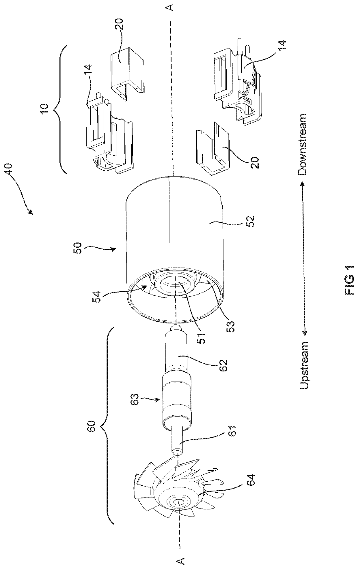
[0023]FIG. 1 shows an exploded perspective view of an electric motor 40. The electric motor 40 comprises a stator assembly 10, and also comprises a frame 50 and a rotor assembly 60. The frame 50 comprises an inner wall 51 and an outer wall 52. The outer wall 52 surrounds the inner wall 51 such that an annular channel 54 is defined between them. A number of diffuser vanes 53 extend between the inner wall 51 and the outer wall 52 through the annular channel 54. The rotor assembly 60 comprises a shaft 61, a magnet 62, a bearing assembly 63 and an impeller 64. When assembled, the magnet 62, bearing assembly 63 and impeller 64 are all fixed directly to the shaft 61 by one or a combination of an interference fit and adhesive. The magnet 62 is a bonded permanent magnet of the sort typically used in permanent magnet brushless motors, and in the example shown the magnet 62 is a four-pole permanent magnet.

[0024]The rotor assembly 60 is supported in the frame 50 by the inner wall 51. The beari...


PUM


Abstract

An electric motor comprising: a frame; and a stator assembly; the stator assembly including a bobbin assembly and at least one c-shaped stator core. The frame comprises at least one lug, the bobbin assembly includes at least one recess, and the stator assembly is fixed to the frame by fixing the lug inside the recess of the bobbin assembly.

Description

REFERENCE TO RELATED APPLICATIONS[0001]This application claims the priority of United Kingdom Application No. 1521890.2, filed Dec. 11, 2015, the entire contents of which are incorporated herein by reference.FIELD OF THE INVENTION[0002]The present invention relates to an electric motor.BACKGROUND OF THE INVENTION[0003]Electric motors typically comprise a rotor assembly, a stator assembly and a frame which holds the components together. The stator assembly is typically mounted to the frame using the iron stator core. This allows the positioning of the stator core relative to other components of the motor, such as the rotor assembly, to be carefully controlled to a very high tolerance. However, using the stator cores in a structural role and for relative positioning in this way requires the stator cores to be made very robust and to a very high tolerance. This can result in stator cores that are bulky, heavy and expensive to manufacture. In addition, the requirement for such stator co...

Claims


Application Information

Patent Timeline
Patent Type & Authority Patents(United States)
IPC IPC(8): H02K3/18H02K1/14H02K3/52H02K21/18H02K37/16H02K15/02H02K1/27H02K7/14
CPCH02K3/18H02K1/141H02K1/143H02K1/27H02K3/524H02K7/14H02K15/028H02K21/18H02K21/185H02K37/16H02K9/06H02K1/185H02K5/04H02K1/14H02K3/52
Inventor LOCKE, SIMON ALEXANDERDYMOND, NIGEL YOUATTBARNES, ANDREW SIMEON
Owner DYSON TECH LTD
Why Eureka
Try Eureka