System and method for delivering sprayed particles by electrospraying

a technology of electrospraying and particles, applied in the direction of electrostatic spraying apparatus, pump control, other medical devices, etc., can solve the problems of affecting the formation of spray at the outlet of the nozzle, affecting the flow of particles, and relatively high surface tension of water

Active Publication Date: 2021-11-16
GILBERT TECH BV
View PDF11 Cites 0 Cited by
  • Summary
  • Abstract
  • Description
  • Claims
  • Application Information

AI Technical Summary

Benefits of technology

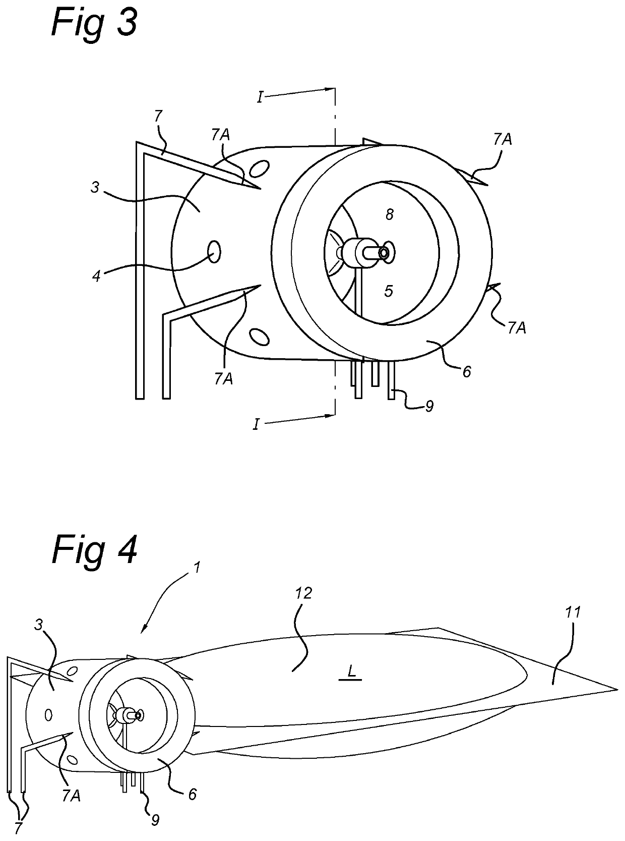
[0011]Advantageously, the discharge electrode is capable of generating a corona discharge which creates an electric wind towards the counter electrode which is substantially parallel to the flow of sprayed particles from the nozzle towards the discharge electrode. The electric wind assists with the propagation of the droplets of spray by increasing the flow rate of the spray and thus shorten the time to administer a dosage to a being.
[0014]Moreover, the electric wind overcomes a further disadvantage from the prior art since in prior art system and method the sprayed particles are charged a deposition of the particles at a nearby surface such as the mouth or tracheal parts of the lung system of the being is very probable which would reduce the dosage of the medicament reaching the desired specific region of the respiratory system.
[0015]Advantageously, the oppositely charged ions in the electric wind will also discharge the particles in the spray making it for the particles possible to penetrate deeply into the respiratory tract without unwanted deposition.

Problems solved by technology

However, it is observed in prior art such a spraying device the flow of particles may be quite limited.
In particular, water has a relatively high surface tension, which adversely affects the formation of a spray at the outlet of the nozzle.
For water as carrying liquid, the electric field strength has to be so high that discharges are generated between nozzle and counter electrode that disturb the spray formation and interfere with a proper use for administering water based medicaments.

Method used


Image

  • System and method for delivering sprayed particles by electrospraying
  • System and method for delivering sprayed particles by electrospraying
  • System and method for delivering sprayed particles by electrospraying

Examples


Embodiment Construction

[0050]In the following figures, the same reference numerals refer to similar or identical components in each of the figures.

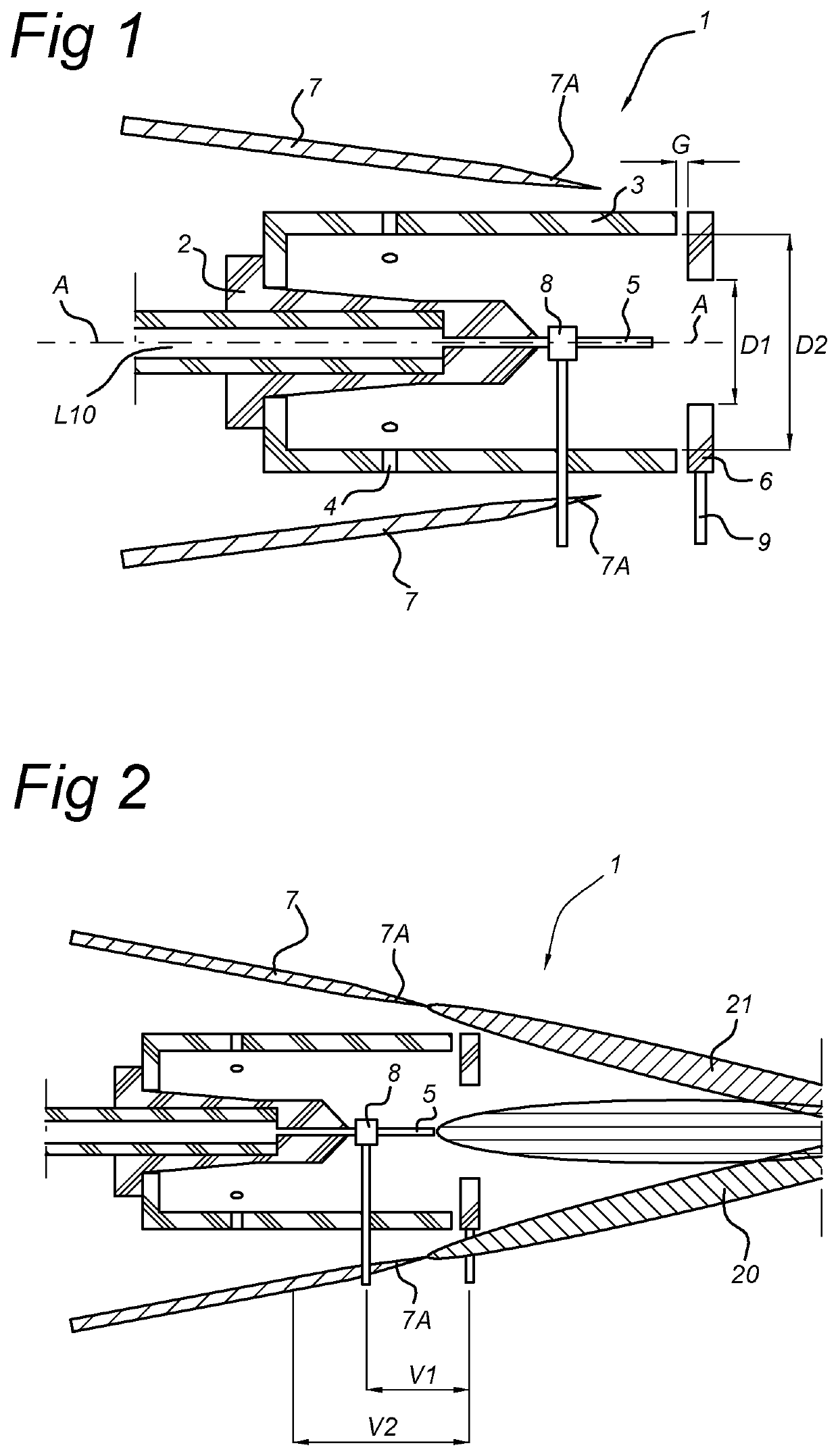
[0051]FIG. 1 shows a cross-sectional view of a spraying device according to an embodiment of the invention.

[0052]In the embodiment, the spraying device 1 comprises a nozzle with an inlet assembly 2 and an outlet 5, i.e. a hollow needle. The inlet assembly 2 is coupled to a storage volume (not shown) through a connection, e.g., a tube 10.

[0053]Further the inlet assembly 2 comprises an insulating wall element 3, preferably a cylindrical wall element 3, that surrounds and is parallel to the nozzle outlet 5. In an embodiment, the main body axis of the cylindrical wall element is arranged to coincide with the longitudinal axis of the nozzle.

[0054]The cylindrical wall element 3 has an open end surface proximate to the location of the nozzle outlet 5. Also, the cylindrical wall element 3 may comprise one or more openings 4 in the cylindrical wall and / or an open end su...


PUM

PropertyMeasurementUnit
pulse frequencyaaaaaaaaaa
voltageaaaaaaaaaa
pressureaaaaaaaaaa

Abstract

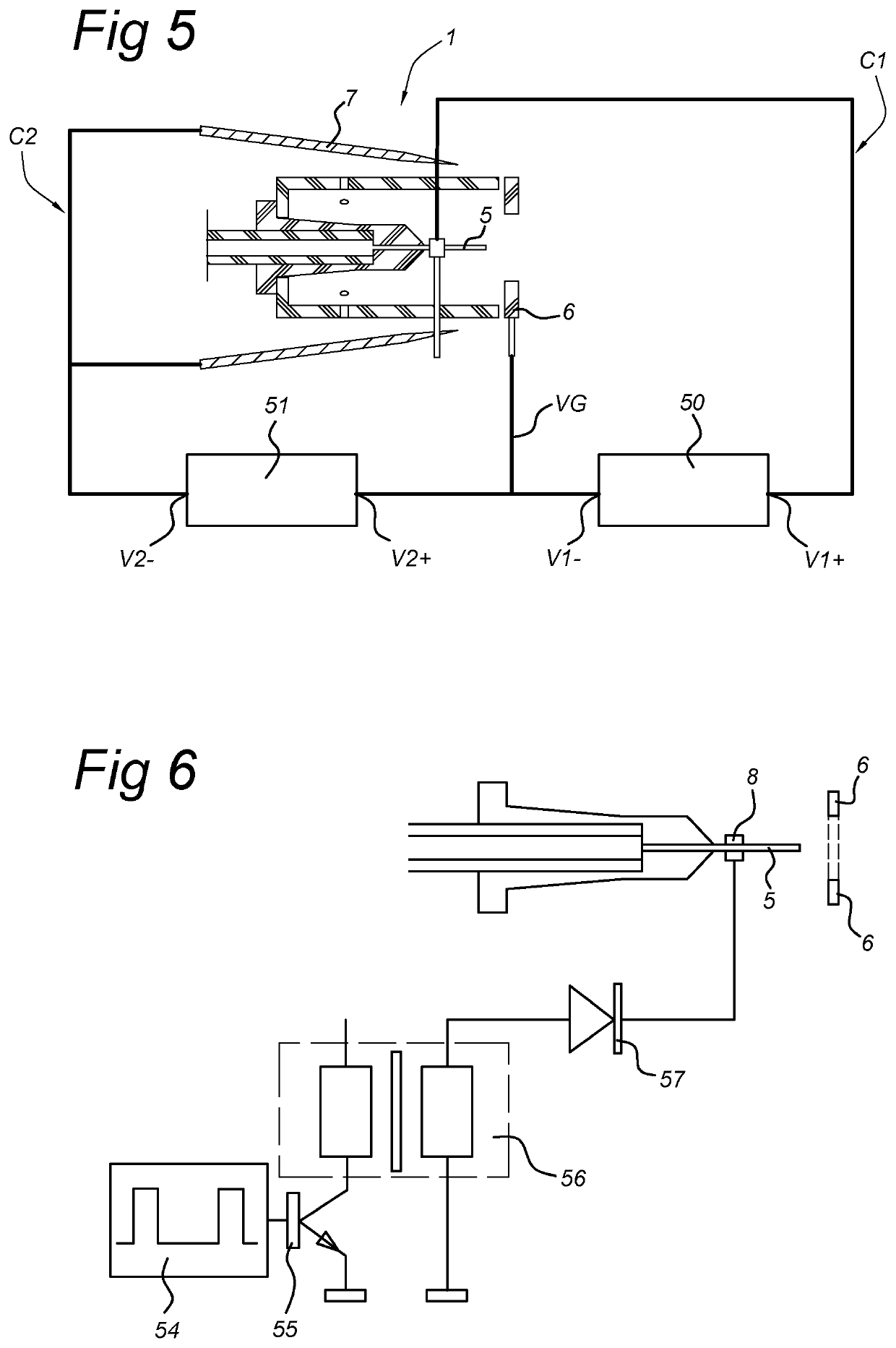
A spraying device for producing a spray of particles in a carrier gas at ambient pressure, includes a storage volume for a liquid substance; at least one nozzle having an inlet and an outlet, the nozzle inlet fluidly communicating with the storage volume; a counter electrode; an electric supply coupled between the at least one nozzle and counter electrode for providing a first potential and create a first electric field between the nozzle outlet and the counter electrode. The device further includes at least one discharge electrode coupled to the electric supply for providing a second potential between the discharge electrode and the counter electrode, the polarity of the second potential being opposite to the polarity of the first potential. The at least one nozzle and the at least one discharge electrode are arranged adjacent and parallel to each other and facing the counter electrode from a substantially same direction.

Description

FIELD[0001]The present invention relates to a system for delivering sprayed particles by electrospraying. Also, the present invention relates to a method for delivering sprayed particles by electrospraying.BACKGROUND[0002]Electrospraying is a process where a liquid can be distributed into uniformly sized particles under the influence of an electrical field. From a reservoir liquid is transported into a nozzle. The nozzle is coupled to one polarity of a high voltage source and functions as an electrode. A counter electrode is typically formed by a plate or mesh at some distance from the nozzle electrode, and is coupled to the other polarity of the high voltage source. By creating a high voltage between the nozzle and the counter electrode a liquid droplet at the tip of the nozzle becomes charged and atomizes due to the electrostatic forces. The atomized and charged liquid particles in the electric field between the nozzle and the counter electrode form a flow of particles, i.e., a sp...

Claims


Application Information

Patent Timeline
Patent Type & Authority Patents(United States)
IPC IPC(8): B05B5/03B05B5/053A61M15/02B05B5/025
CPCB05B5/032A61M15/02B05B5/0255B05B5/0535A61M2202/0468F04C2270/0421
Inventor ROOS, REIN ANDREYURTERI, CANER UMITMARIJNISSEN, JOHANNES CORNELIS MARIA
Owner GILBERT TECH BV
Why Eureka
Try Eureka