
Trimmer head and spool for a trimmer head

a technology of trimmer head and spool, which is applied in the field of trimmer head, can solve the problems of line portions that project from the head being subject to wear and can break

Active Publication Date: 2021-09-07
ARNETOLI MOTOR
View PDF9 Cites 1 Cited by
  • Summary
  • Abstract
  • Description
  • Claims
  • Application Information

AI Technical Summary

Benefits of technology

The patent describes a trimmer head for a trimmer apparatus. The trimmer head has a housing with two end walls and a side wall, between which a spool is placed and pushed by a spring to a first position. The trimmer head also has a ring member with inclined teeth that cooperate with projections on the spool or the housing to prevent spool rotation in one direction and cause the spool to move axially in the opposite direction. This allows the spool to move between two positions without changing the direction of rotation. The technical effect of this design is a more stable and accurate trimming process.

Problems solved by technology

The line portions that project from the head are subject to wear and can break.

Method used


Image

  • Trimmer head and spool for a trimmer head
  • Trimmer head and spool for a trimmer head
  • Trimmer head and spool for a trimmer head

Examples


first embodiment

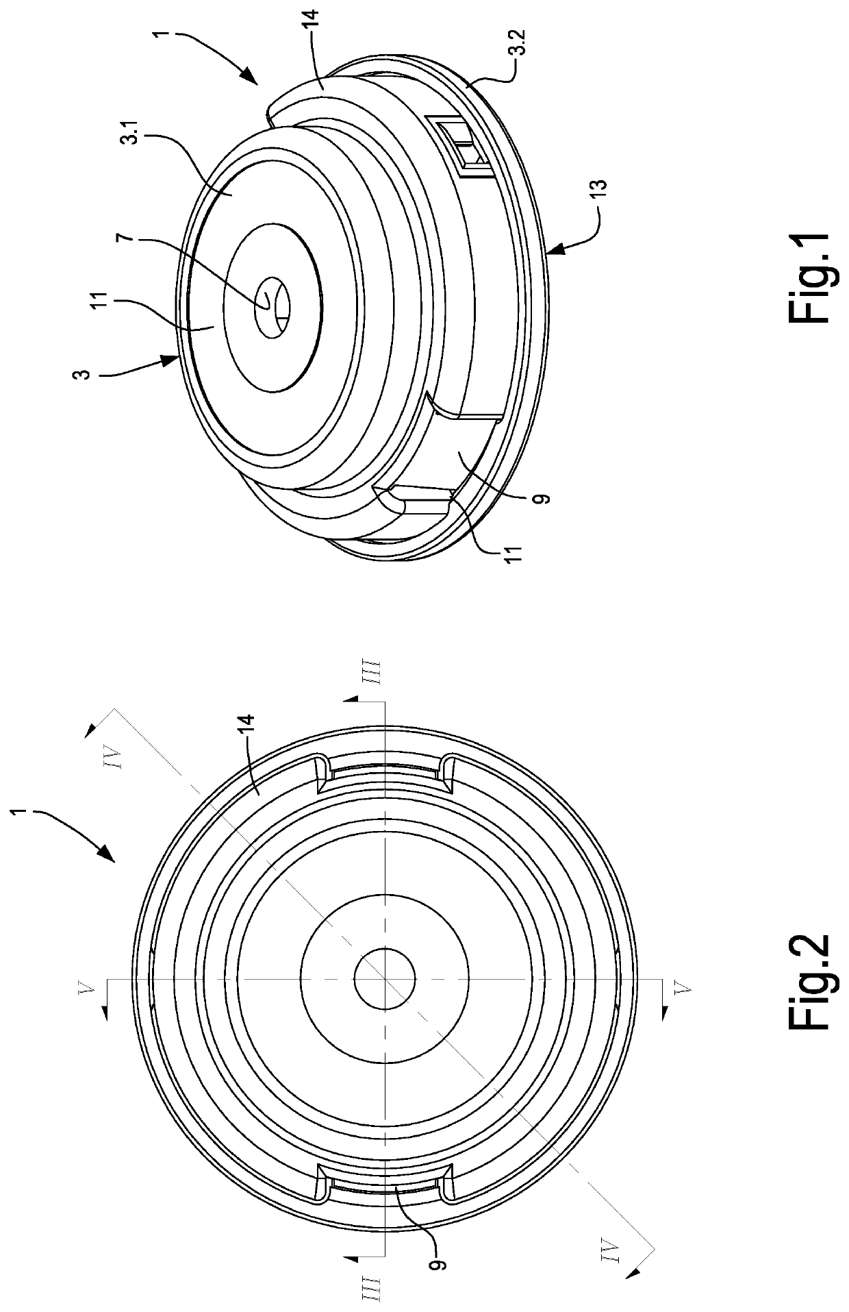
[0048]a trimmer head according to the present disclosure is illustrated in FIGS. 1 to 21.

[0049]More in particular FIGS. 1 to 8 show the trimmer head overall with a spool mounted inside it, while FIGS. 9 to 14 illustrate the spool separate from the trimmer head housing and FIGS. 15 to 21 illustrate the lower portion or lid of the trimmer head housing with assembled thereon one or the other of the two ring members that provide the inclined teeth with which the spool cooperates.

[0050]With initial reference to FIGS. 1 to 8, in one embodiment the trimmer head, indicated overall by 1, comprises a housing 3, inside which a spool 5 is arranged, on which a trimmer line is wound forming a plurality of coils inside a winding space formed in the spool 5. The trimmer line is shown schematically only in FIG. 5 and indicated therein by F.

[0051]In some embodiments, as illustrated in the drawing, the housing 3 comprises a first portion 3.1, below referred to as upper portion 3.1, and a second portio...


PUM


Abstract

The trimmer head (1) includes a housing (3) and a spool (5) that can be housed in the housing. A pair of ring members (35A, 35B) with teeth inclined at opposite inclinations can be selectively coupled to the head, to engage the trimmer head (1) in combination with trimmer apparatuses having engine that rotates selectively in a clockwise or anticlockwise direction.

Description

TECHNICAL FIELD[0001]The present disclosure concerns gardening accessories. More specifically, the present disclosure concerns trimmer heads and in particular line trimmer heads.BACKGROUND ART[0002]Gardening trimmer heads are used for cutting grass and other vegetation. The trimmer heads are applied to the rotary shaft of a trimmer apparatus to rotate at high speed. A trimmer line, wound in a spool inside the head, projects from openings on the head and forms cutting members which are tensioned due to the centrifugal force. The line portions that project from the head are subject to wear and can break. When this happens, further trimmer line must be delivered in order to restore the projecting portion. When the line supply wound on the spool runs out, a new line supply must be wound in the head. This can be done without opening the trimmer head, by reciprocally rotating the housing and the spool positioned inside it. To rewind the trimmer line, the spool must be rotated in one singl...

Claims


Application Information

Patent Timeline
Patent Type & Authority Patents(United States)
IPC IPC(8): A01D34/416
CPCA01D34/4166A01D34/4163A01D34/4161A01D34/4165
Inventor ARNETOLI
Owner ARNETOLI MOTOR
Learn More