Driving force control system for vehicle

a technology of driving force control and control system, which is applied in the direction of control devices, driver input parameters, vehicle components, etc., can solve the problems of not having a torque generating device, affecting the driving experience, so as to reduce the slip ratio, eliminate the slippage of the wheel, and prevent the effect of feeling

Active Publication Date: 2021-08-31
TOYOTA JIDOSHA KK
View PDF1 Cites 1 Cited by
  • Summary
  • Abstract
  • Description
  • Claims
  • Application Information

AI Technical Summary

Benefits of technology

[0005]Aspects of embodiments of the present disclosure have been conceived noting the foregoing technical problems, and it is therefore an object of the present disclosure to provide a driving force control system for a vehicle configured to eliminate slippage of a pair of wheels without changing a driving torque or a braking torque abruptly.
[0010]Thus, according to the exemplary embodiment of the present disclosure, the torque generating device is arranged on an input side of the differential mechanism that distributes torque to the right wheel and the left wheel. As described, the controller restricts the differential rotation between the right wheel and the left wheel less than the predetermined value by the differential mechanism. In addition, if the slip ratio of one of the wheels that is smaller than the slip ratio of the other one of the wheels is greater than an acceptable value, the controller executes the slip-eliminating control to restrict the torque generated by the torque generating device thereby reducing the slip ratio of one of the wheel whose slip ratio is smaller than the slip ratio of the other one of the wheels. According to the exemplary embodiment of the present disclosure, therefore, the torque of the torque generating device will not be changed abruptly when eliminating slippage of the wheel. For this reason, the driver may be prevented from feeling uncomfortable feeling when eliminating the slippage. In addition, the driving torque and the braking torque will not be applied individually to each driveshaft simultaneously. For this reason, an occurrence of resonance of the driveshafts may be prevented. Further, since only one of the right wheel and the left wheel whose slip ratio is smaller than the other one is controlled to eliminate the slippage, the driving torque and the braking torque will not be reduced excessively.

Problems solved by technology

However, the vehicle described in JP-A-2004-351945 is not provided with a torque generating device for generating a braking torque in a transmission route between a prime mover and drive wheels.
If the clutch device is disengaged or the transmission torque of the clutch device is reduced in the event of slippage of the wheel, the torques of the right wheel and the left wheel may be imbalanced and changed abruptly.

Method used


Image

  • Driving force control system for vehicle
  • Driving force control system for vehicle
  • Driving force control system for vehicle

Examples


Embodiment Construction

)

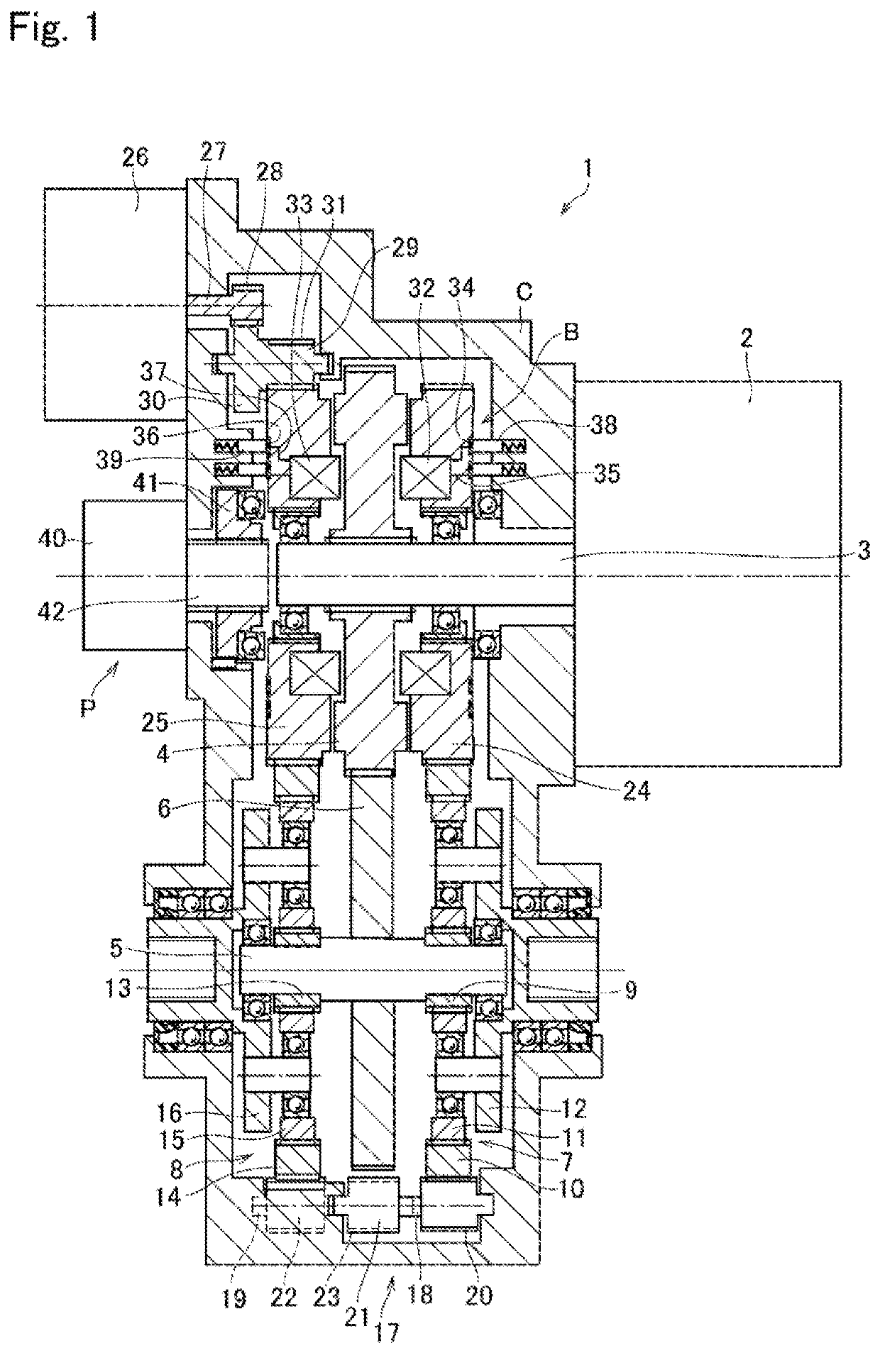
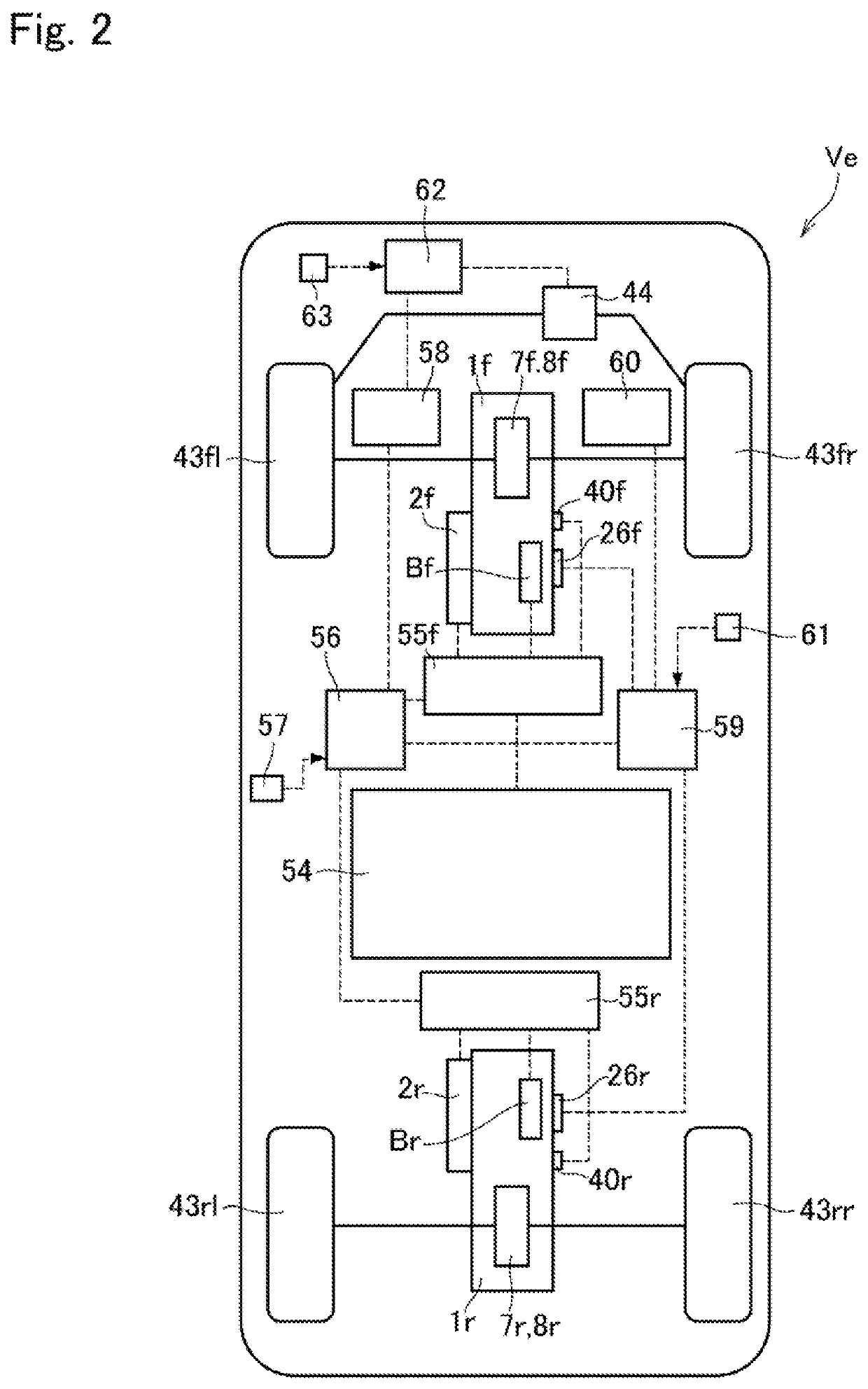
[0028]An exemplary embodiment of the present disclosure will now be explained with reference to the accompanying drawings. Referring now to FIG. 1, there is schematically shown a structure of a drive unit 1 of a vehicle Ve to which the driving force system according to the preferred embodiment of the present disclosure is applied. The drive unit 1 comprises: a torque generating device that generates a driving torque or a braking torque; a differential mechanism that distributes the torque generated by the torque generating device to a right wheel and a left wheel; and a differential restricting device that restricts a differential rotation between the right wheel and the left wheel.

[0029]As illustrated in FIG. 1, the drive unit 1 is provided with a drive motor 2 serving as a torque generating device of the embodiment of the present disclosure. For example, as a conventional hybrid vehicle and an electric vehicle, a permanent magnet synchronous motor-generator may be adopted as the ...


PUM


Abstract

A driving force control system for a vehicle configured to eliminate slippage of a wheel without changing a driving torque or a braking torque abruptly. The driving force control system comprises a drive unit and a controller. The drive unit includes a differential mechanism connected to a right wheel and a left wheel to distribute torque of a torque generating device, and a differential restricting device that restricts a differential rotation between the right wheel and the left wheel. The controller restricts a differential rotation between the right wheel and the left wheel less than a predetermined value by the differential mechanism. If a slip ratio of one of the wheels smaller than that of the other wheels is greater than an acceptable value, the controller executes a slip-eliminating control.

Description

CROSS REFERENCE TO RELATED APPLICATIONS[0001]The present application claims the benefit of priority to Japanese Patent Application No. 2018-235713 filed on Dec. 17, 2018 with the Japanese Patent Office, the entire contents of which are incorporated herein by reference in its entirety.BACKGROUNDField of the Invention[0002]Present disclosure relates to the art of a driving force control system for a vehicle that controls a driving force and a braking force of the vehicle in the event of slippage of a wheel.Discussion of the Related Art[0003]JP-A-2004-351945 describes a control system for a vehicle comprising: a front power transmission route for delivering a torque of a prime mover to a pair of front wheels; a rear power transmission route for delivering a torque of the prime mover to a pair of rear wheels; and a clutch device that controls transmission torques of the front power transmission route and the rear power transmission route. In the event of slippage of any one of the pair ...

Claims


Application Information

Patent Timeline
Patent Type & Authority Patents(United States)
IPC IPC(8): B60K17/16B60W30/18
CPCB60W30/18172B60K17/165B60W2520/10B60W2520/266B60W2520/30B60W2710/12B60W2720/266B60W30/20B60K23/04B60W2720/403B60W2720/26B60W2520/26B60W2540/18B60W2520/28B60W2710/083
Inventor OTA, JUNYAISONO, HIROSHI
Owner TOYOTA JIDOSHA KK
Why Eureka
Try Eureka