Eureka AIR delivers breakthrough ideas for toughest innovation challenges, trusted by R&D personnel around the world.

Adaptive boundary wire transmitter

a transmitter and boundary wire technology, applied in the direction of vehicle position/course/altitude control, process and machine control, instruments, etc., can solve the problems of time-consuming, time-consuming, and inflexible, and achieve the effect of high-quality output signals without the need for time-consuming calibration

Active Publication Date: 2021-07-27
GLOBE (JIANGSU) CO LTD
View PDF37 Cites 0 Cited by
  • Summary
  • Abstract
  • Description
  • Claims
  • Application Information

AI Technical Summary

Benefits of technology

The patent describes a device called an adaptive boundary wire transmitter that can automatically adjust to different lengths of boundary wires and guide wires without the need for calibration. It uses two power amplifiers, a sensing element, a feedback amplifier, a compensation network, and an error amplifier to create a high-quality output signal. The technical effect of this device is that it simplifies the installation process and ensures consistent quality across different boundary wire lengths.

Problems solved by technology

This calibration process may be time-consuming.
The signal may be calibrated when the system is installed, which is, as mentioned above, time-consuming.
However, this is not very flexible, since the length of the border delimitation needs to be adapted to each specific installation.

Method used


Image

  • Adaptive boundary wire transmitter
  • Adaptive boundary wire transmitter
  • Adaptive boundary wire transmitter

Examples


Embodiment Construction

[0018]In the following, a detailed description of exemplary embodiments of an adaptive boundary wire transmitter according to the present invention for will be presented.

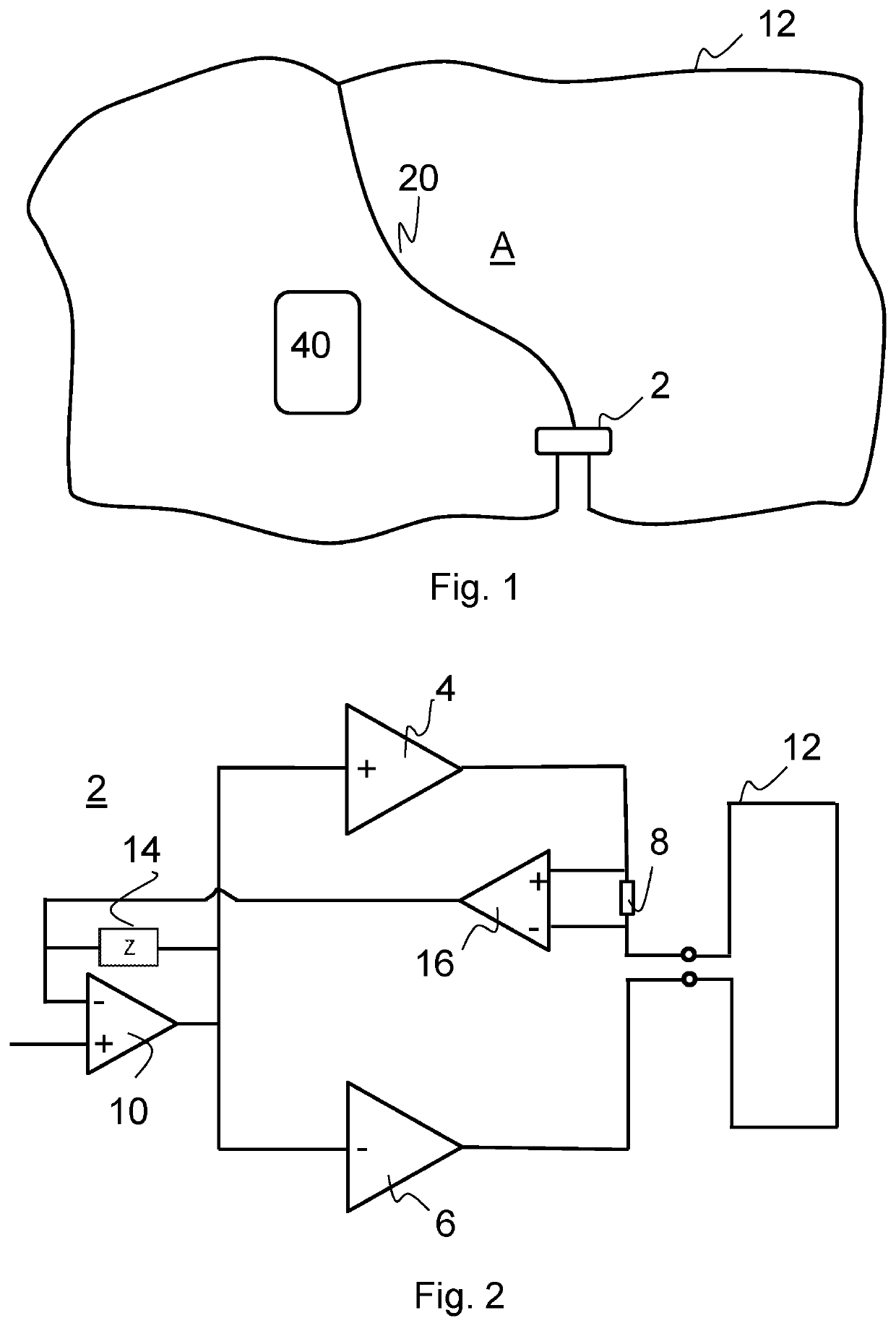
[0019]First a general description of a robotic lawnmower system will be made. FIG. 1 shows a robotic lawnmower 40 which is arranged move across an area A surrounded by a boundary wire 12. As is obvious the lawnmower 40 is depicted somewhat enlarged for the sake of clarity. The boundary wire 12 may be configured in any way, such that it delimits the area A within which the robotic lawnmower 40 is allowed to move. The boundary wire 12 is preferably provided under the ground in the lawn, such that is not visible, but may also be provide on or above the ground. The boundary wire 12 could be an ordinary copper wire of single-core type. There are of course also other options, which is well-known by a person skilled in the art, such as multi stranded wire types. The system also comprises a signal generator which feeds a tr...


PUM


Abstract

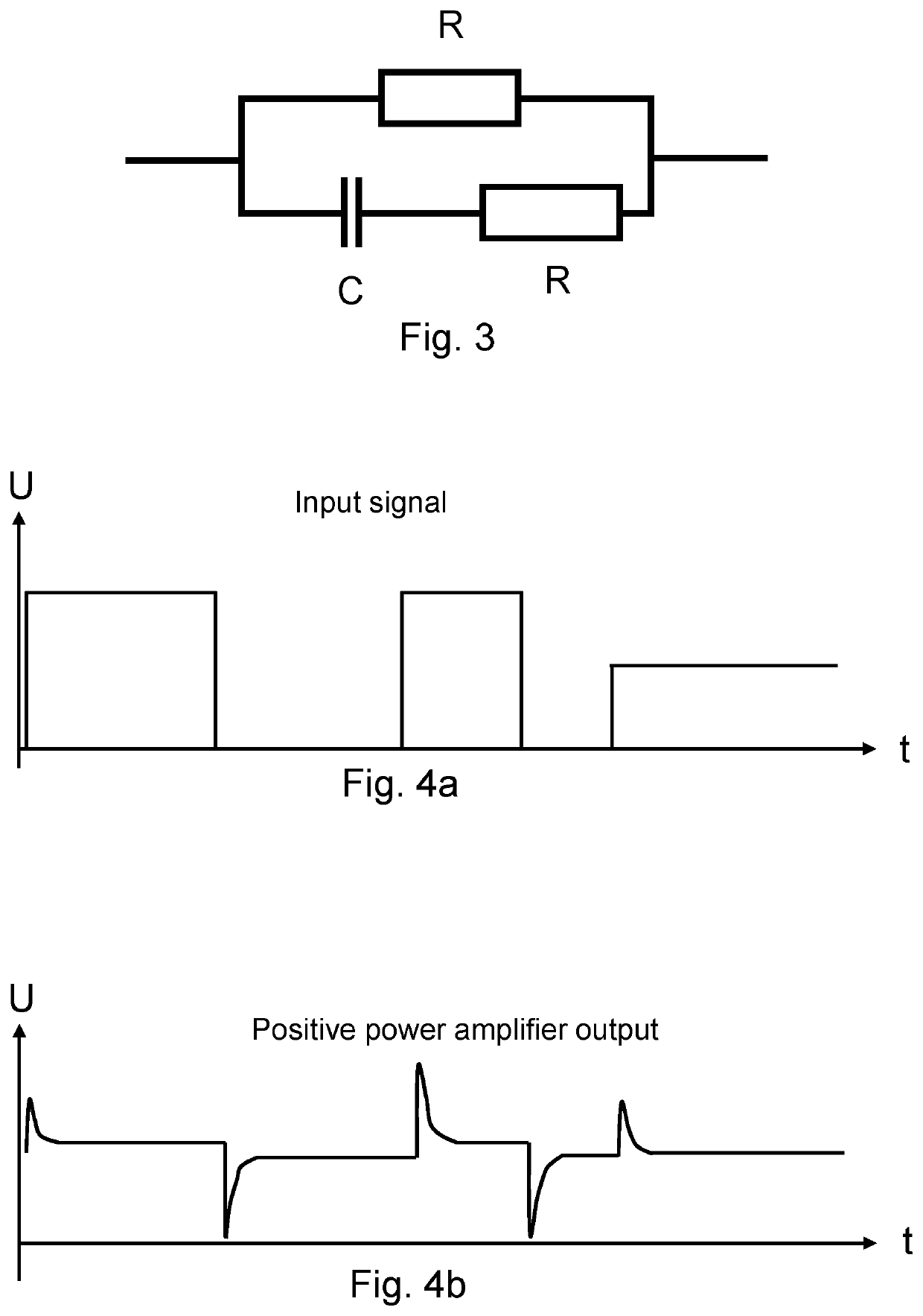
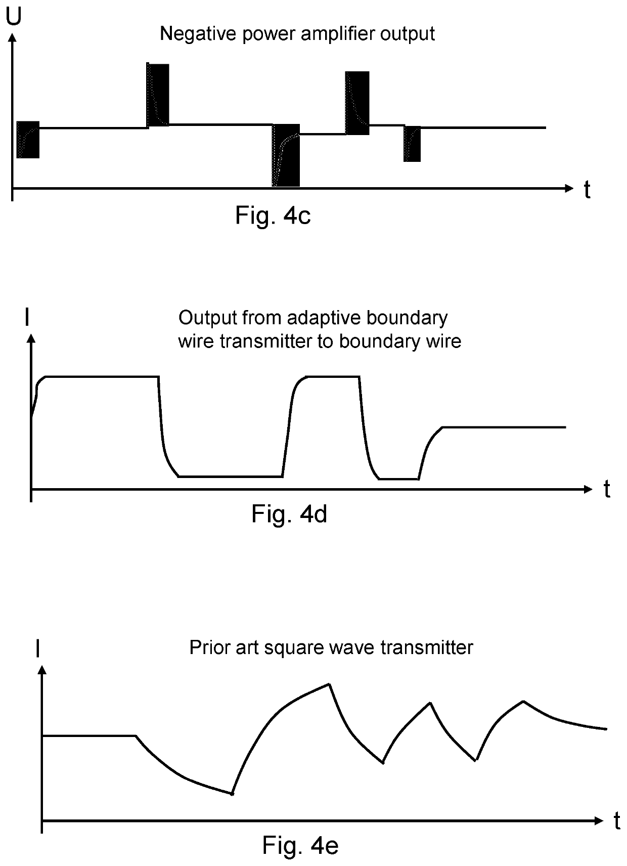
An adaptive boundary wire transmitter includes two bridge coupled power amplifiers, a sensing element, a feedback amplifier, a compensation network and an error amplifier. The adaptive boundary wire transmitter is connected to a boundary wire installation, including a boundary wire and feeds the boundary wire with a boundary signal current. By using a feedback amplifier to which the boundary signal current is fed together with the input signal together with compensation network and an error amplifier it is possible to generate a stable output signal from the adaptive boundary wire transmitter to the boundary wire that is independent of the boundary wire length.

Description

TECHNICAL FIELD[0001]The present invention relates generally to a transmitter for powering a boundary wire installation used for keeping a robotic lawnmower within an area surrounded by a boundary wire, and more specifically a transmitter that is adaptive to properties of the boundary wire installation.BACKGROUND ART[0002]In prior art, robotic lawnmowers are generally known. For example, EP 1 025 472 discloses a battery-operated lawnmower having a control unit for determining the travel direction and speed of the lawnmower. The surface to be mowed is defined by a border delimitation wire. Two signals with alternating voltage are applied simultaneously by a signal generator to the border delimitation wire. These signals are detected by receiving coils in the lawnmower and evaluated in order to decide if the lawnmower is located within or outside the border delimitation wire. The quality of these signals is important in order to make a correct decision regarding the position of the la...

Claims


Application Information

Patent Timeline
Patent Type & Authority Patents(United States)
IPC IPC(8): G05D1/02
CPCG05D1/0265G05D2201/0208
Inventor ALZEN, JIMMY
Owner GLOBE (JIANGSU) CO LTD
Why Eureka
Eureka Blog
Learn More