
Electronic cigarette vaporizer with liquid storage transition chamber

a technology of transition chamber and electronic cigarettes, which is applied in the field of electronic cigarettes, can solve the problems of e-cigarette liquid leakage into the vaporizing chamber through the vaporizing unit, harm to the human body, and leakage of e-cigarette liquid into the vaporizing chamber, and achieve the effect of improving the taste of users

Active Publication Date: 2021-07-06
LIN GUANGRONG
View PDF11 Cites 26 Cited by
  • Summary
  • Abstract
  • Description
  • Claims
  • Application Information

AI Technical Summary

Benefits of technology

The electronic cigarette vaporizer has a special chamber that helps to prevent liquid from leaking and ensures a steady supply of liquid to the vaporizing unit. This results in a better taste for users, as the liquid is supplied quickly and efficiently during smoking. Overall, this design improves the performance of the electronic cigarette and makes it more user-friendly.

Problems solved by technology

Conventional tobacco cigarettes contain tobacco tars which may be introduced into the human body by inhalation during smoking and thus are very harmful to the human body.
However, since the junction part between the vaporizing unit and the liquid storage chamber can hardly be sealed completely, the e-cigarette liquid can be free to flow inside the liquid storage chamber in normal conditions and may leak into the vaporizing chamber through the vaporizing unit under gravity.
In such case, droplets of the e-cigarette liquid may enter the user's mouth during smoking and lead to undesired taste or even a failure.
Moreover, in order to avoid liquid leakage, some existing electronic cigarettes or electronic cigarette vaporizers are additionally arranged with a layer of permeable membrane for obstructing a flow of the e-cigarette liquid between the liquid storage chamber and the vaporizing unit, which membrane however may lead to a short supply of the e-cigarette liquid and result in a lack of sufficient vapor during smoking.

Method used


Image

  • Electronic cigarette vaporizer with liquid storage transition chamber
  • Electronic cigarette vaporizer with liquid storage transition chamber
  • Electronic cigarette vaporizer with liquid storage transition chamber

Examples


Embodiment Construction

[0044]In order to make purposes, technical solutions and advantages of the present invention clearer, the present invention will be further explained in detail with reference to figures and embodiments described hereinafter.

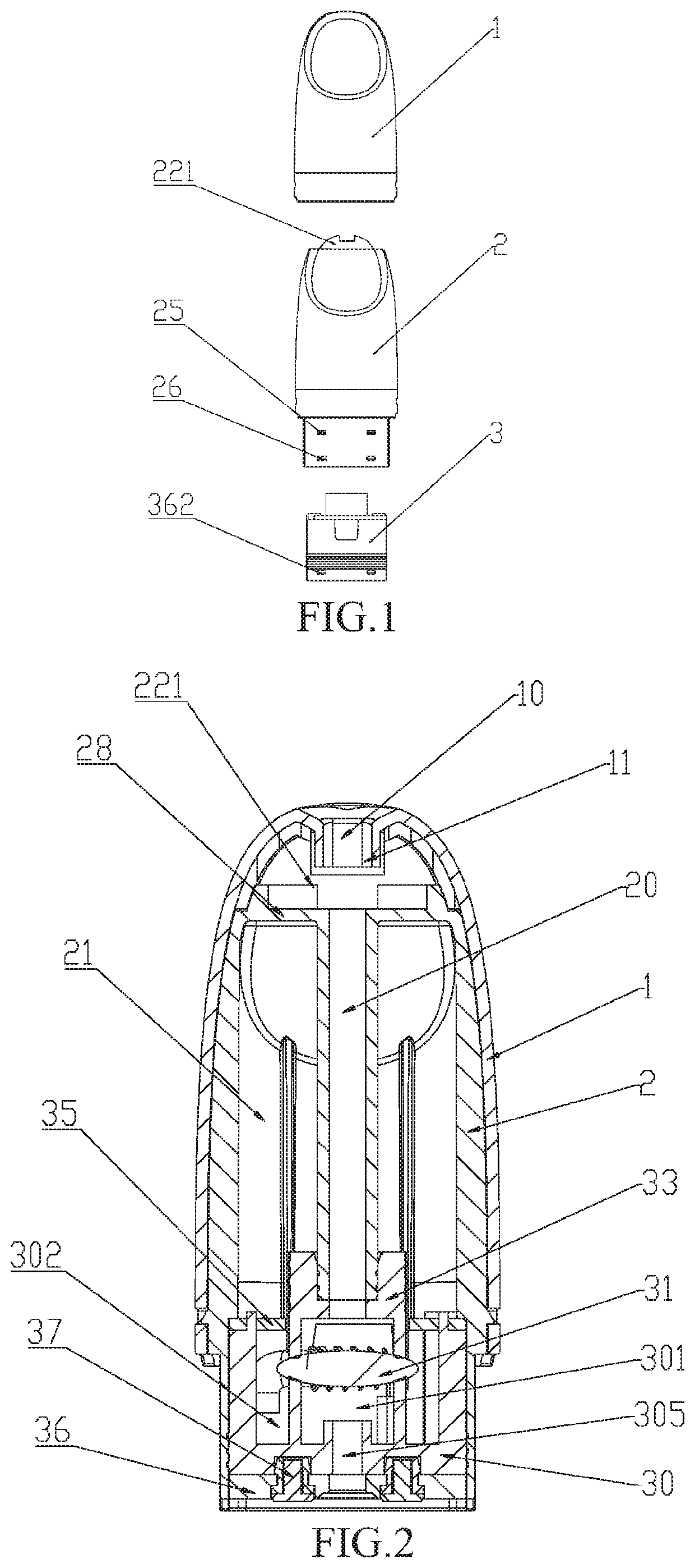
[0045]For convenience of description, the electronic cigarette vaporizer with a liquid storage transition chamber of the present invention is described in a condition that the electronic cigarette vaporizer is vertically disposed with its mouth piece 1 facing upward, as shown in FIG. 1. It should be understood that, as used herein, the expresses such as upper, lower, top, bottom, upper end, lower end, upper side and lower side, are intended to indicate orientation and position relationships in a condition that the electronic cigarette vaporizer is vertically disposed with its mouth piece facing upward.

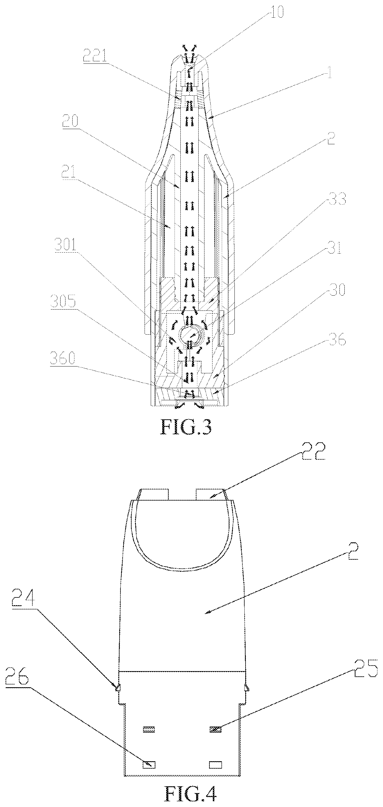
[0046]Referring to FIGS. 1-3, an electronic cigarette vaporizer with a liquid storage transition chamber of the present invention comprises a mouth piece 1, a liqui...


PUM


Abstract

An electronic cigarette vaporizer with a liquid storage transition chamber comprises a liquid reservoir comprising an upper wall at its top end and a vapor outlet tube extends downwards from the center of the upper wall, and a vaporizing device comprising a vaporizing base sleeved in the lower part of the liquid reservoir, and a liquid storage chamber is defined above the vaporizing device between the liquid reservoir and the vapor outlet tube; and inner and outer chambers sealed from each other are formed inside the vaporizing base, the inner chamber mounted with a vaporizing unit serves as a vaporizing chamber, and the outer chamber filled with liquid storage medium serves as a liquid storage transition chamber, wherein the vaporizing chamber communicates with the vapor outlet tube, and the liquid storage transition chamber communicates with the liquid storage chamber so as to supply liquid for the vaporizing unit.

Description

FIELD OF THE INVENTION[0001]The present invention relates to the technical field of electronic cigarettes, and in particular, the present invention relates to an electronic cigarette vaporizer with a liquid storage transition chamber.BACKGROUND OF THE INVENTION[0002]Conventional tobacco cigarettes contain tobacco tars which may be introduced into the human body by inhalation during smoking and thus are very harmful to the human body. The electronic cigarettes usually heat the e-cigarette liquid by means of a vaporizing device, to produce vapor for the smoker. Since the e-cigarette liquid does not contain the tobacco tar, the e-cigarettes are widely used and gradually replace the tobacco cigarettes.[0003]Existing electronic cigarettes and electronic cigarette vaporizers usually are arranged with a liquid storage chamber for storing the e-cigarette liquid, and the vaporizing device may be arranged with a the vaporizing unit, by means of which the e-cigarette liquid directly absorbed f...

Claims


Application Information

Patent Timeline
IPC IPC(8): A24F13/00A24F17/00A24F25/00A24F40/42A24F40/48A24F40/46A24F40/485A24F40/10A24F15/015
CPCA24F40/42A24F40/46A24F40/48A24F40/485A24F15/015A24F40/10
Inventor LIN, GUANGRONGZHENG, XIANBIN
Owner LIN GUANGRONG
Learn More