
Downdraft air cleaning unit and cooking system having the same

a technology of air cleaning unit and cooking system, which is applied in the direction of domestic stoves or ranges, lighting and heating apparatus, heating types, etc., can solve the problems of deteriorating the appearance of the kitchen, large installation space, and affecting the service life of the unit, so as to improve the service life, prevent contamination, and utilize space more efficiently

Active Publication Date: 2021-05-18
LG ELECTRONICS INC
View PDF15 Cites 0 Cited by
  • Summary
  • Abstract
  • Description
  • Claims
  • Application Information

AI Technical Summary

Benefits of technology

[0012]It is an object of the present disclosure to provide a downdraft air cleaning unit that is accommodated in a cooking unit while it is not in use, and is exposed only when it is in use, thereby preventing contamination, utilizing space more efficiently, and improving the service life.
[0013]It is another object of the present disclosure to provide a downdraft air cleaning unit having a suction part which can pivot along the direction in which the contaminated air flows to thereby efficiently suck the air.
[0014]It is another object of the present disclosure to provide a downdraft air cleaning unit in which a lighting device used for checking the doneness of food is mounted on the suction part that can pivot, which allows for efficient lighting and does not disturb cooking when it is not in use.

Problems solved by technology

Unfortunately, such an existing ventilation hood has problems in that it requires a large space for installation and deteriorates the appearance of the kitchen.
However, the downdraft type range hood also has problems in that it is exposed above the cooking unit and thus occupies a large space even when it is not in use, and that it also deteriorates the appearance of the kitchen.
In addition, the existing range hood is exposed above the cooking unit even when it is not in use, and thus it may be contaminated by oil stains generated during cooking or as food is spattered.
Therefore, it is not hygienic, is very troublesome to clean, and has a problem of shortening the life time of the range hood.
In addition, the suction part of the existing range hood is stationary and accordingly it cannot efficiently suck contaminated air generated during cooking if the air is moving.
Accordingly, even when the range hood is not in use, the hood and the protruding position of the lamp interfere with the cooking.
Further, there is a problem in that the lamp is fixed only at a specific position, such that it cannot provide efficient illumination.

Method used


Image

  • Downdraft air cleaning unit and cooking system having the same
  • Downdraft air cleaning unit and cooking system having the same
  • Downdraft air cleaning unit and cooking system having the same

Examples


Embodiment Construction

[0033]Terms and words used in the present specification and claims are not to be construed as a general or dictionary meaning but are to be construed meaning and concepts meeting the technical ideas of the present invention based on a principle that the inventors can appropriately define the concepts of terms in order to describe their own inventions in the best way. Therefore, while the present invention is described with reference to the certain particular embodiments and the accompanying drawings, it is to be understood that the embodiments are merely illustrative and various equivalents and modifications are possible without departing from the spirit and scope of the present disclosure as defined in the following claims.

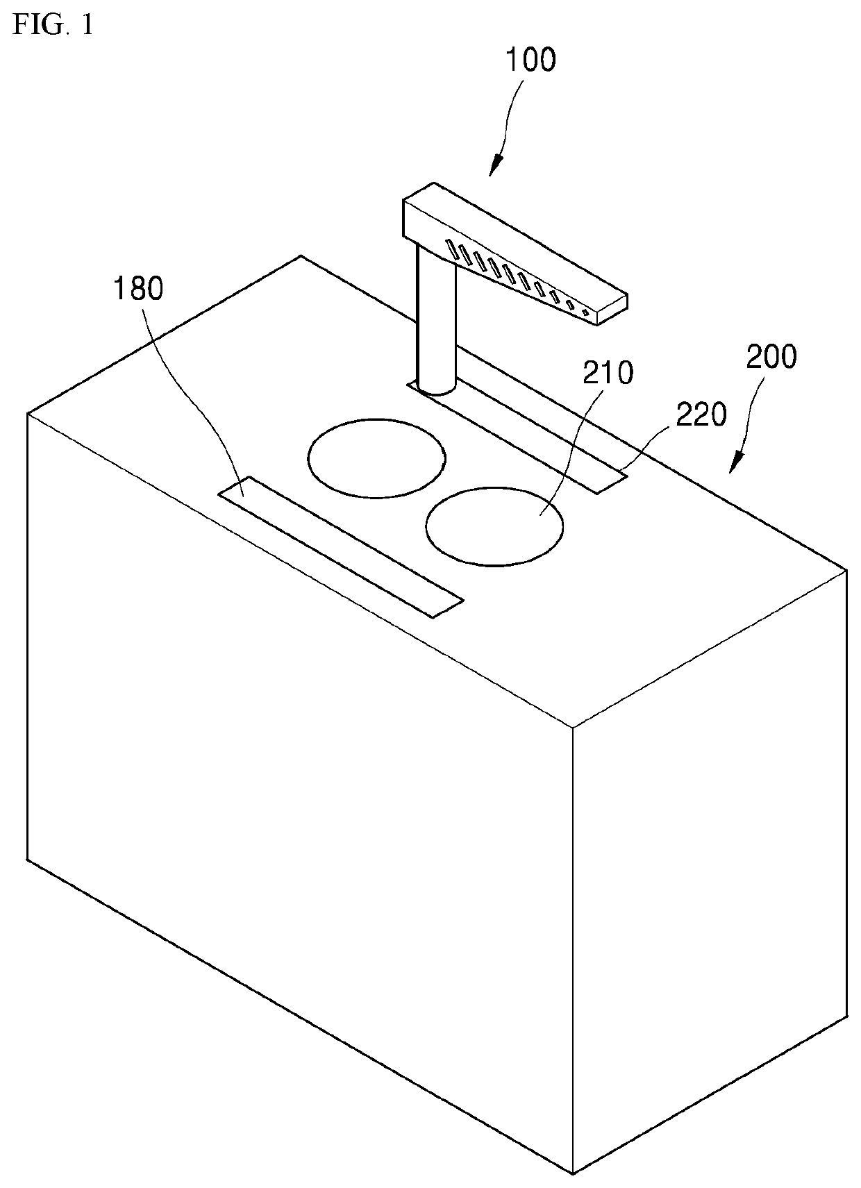
[0034]FIG. 1 is a view schematically showing a downdraft air cleaning unit according to an exemplary embodiment of the present disclosure mounted on a cooking unit.

[0035]As shown in FIG. 1, a downdraft air cleaning unit 100 is mounted on a cooking unit 200 equipp...


PUM


Abstract

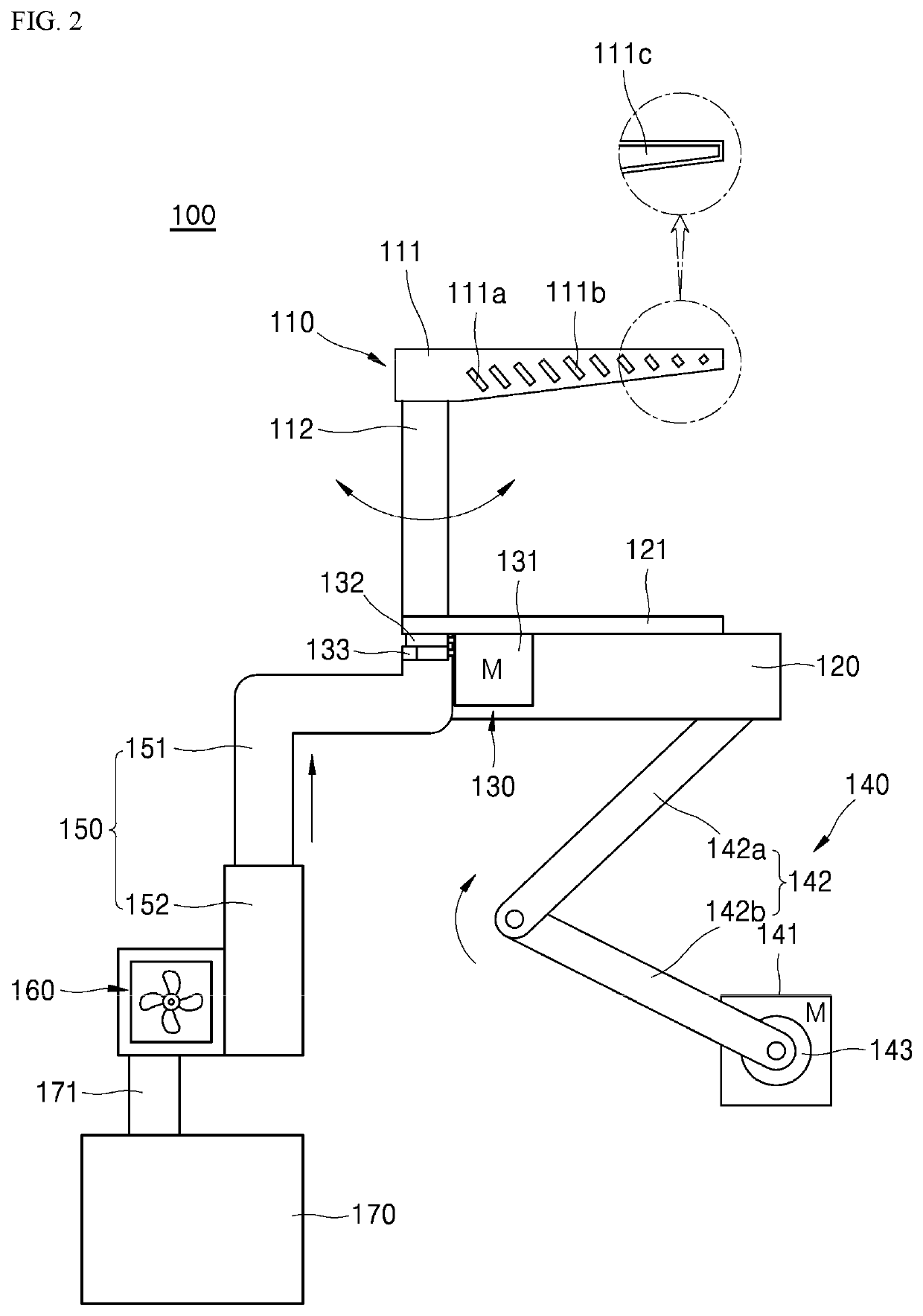
An air cleaning unit includes a suction part into which contaminated air flows, a transfer body coupled with the suction part to support the suction part and to be raised up and down with the suction part; an elevation part connected to the transfer body and raising up and down the transfer body, a pivoting part connected to the suction part to pivot the suction part, and a filtering part communicating with the suction part and cleaning the contaminated air introduced into the suction part.

Description

CROSS-REFERENCE TO RELATED APPLICATIONS[0001]This application claims priority to Korean Patent Application No. 10-2017-0053989, filed on Apr. 26, 2017, in the Korean Intellectual Property Office, the disclosure of which is hereby incorporated by reference in its entirety.BACKGROUND1. Technical Field[0002]The present disclosure relates to a downdraft air cleaning unit and a cooking system including the same. More specifically, the present disclosure relates to a downdraft air cleaning unit capable of efficiently sucking contaminated air generated during cooking, including a suction part that is raised up and down and that pivots, thereby increasing the efficiency of space utilization and providing convenience of operation while preventing contamination.2. Description of the Related Art[0003]Typically, a ventilation hood is installed above a cooking appliance such as a gas range, for forcibly sucking the odor and heat generated during cooking, and for discharging them to the outside.[...

Claims


Application Information

Patent Timeline
Patent Type & Authority Patents(United States)
IPC IPC(8): F24C15/20
CPCF24C15/2042F24C15/2035F24C15/2092F21V33/0044H05B6/1209F24F2221/02F24F2221/10F24F8/10
Inventor KIM, WAN SOOKIM, YANGKYEONGCHOI, WOO JIN
Owner LG ELECTRONICS INC
Learn More