
Portable device for direct shear express field test

a portable device and field test technology, applied in the field of direct shear test portable devices, can solve the problems of preventing meaningful readings, introducing errors, and large size of existing laboratory direct shear test machines, and achieves the effects of convenient use, low cost, and easy understanding

Active Publication Date: 2021-05-11
SCHWARTZ ROBERT M
View PDF17 Cites 0 Cited by
  • Summary
  • Abstract
  • Description
  • Claims
  • Application Information

AI Technical Summary

Benefits of technology

[0004]The present invention is a portable device that in case of testing soft or granular materials can be manufactured from light weight plastic (less than pound), it is small in size (in a preferred embodiment approximately 3 inch×3 inch×3 inch) and relatively inexpensive to manufacture. This present invention will allow a user to perform express field tests during preliminary site exploration for development, repair, or maintenance, sub-surface exploration, space missions to other planets, disaster relief, emergency works, sapper (combat engineering), and quality control of materials delivered on site, construction excavation, dredging, or embankment / dam works to help provide early identification of slope failure possibility. Excavation at construction sites, in particular, is recognized as one of the most hazardous construction operations. Occupational Safety and Health Administration (OSHA) has revised Subpart P, Excavations, of 29 CFR 1926.650, 29 CFR 1926.651, and 29 CFR 1926.652 to make the standard easier to understand, permit the use of performance criteria where possible, and provide construction employers with options when classifying soil and selecting employee protection methods—to utilize different soil testing techniques and quoting the sloping and benching of sides as number one suggested method. These requirements are also reflected in the National Bureau of Standards Report BSS-121 as preferred by contractors.
[0011]With the present invention, the soil testing can now be performed at the job site, without having to transport the soil sample from a remote location to where the test equipment is located. Further, the testing of multiple soil samples can now be performed quickly at the job site, using the present invention, and the test readings can be calculated at the job site or by engineers based on data obtained from the remote location / job site, timely, with reasonably accurate results. Use of the present invention at the job site reduces the previous time it took to get test results and with the reduced time to test the soil, workers do not have to be idle at the job site while waiting for test results and expensive machinery and equipment will not remain idle. Thus, the safety of the workers, preservation of equipment and the integrity of the job site can be maintained quickly and efficiently, with on job site testing and measuring capabilities provided by the present invention.

Problems solved by technology

Existing devices apply a vertical load, then find maximum corresponding horizontal load which causes failure.
Existing laboratory direct shear test machines have significant size, with table top machines being 30 to 44 inches in length, are heavy, with a weight or 140 to 180 pounds are relatively expensive $12,000 and are essentially immobile.
These machines typically have carriage movement, required by known arrangement of the machine, which necessarily introduces errors, due in large measure to the friction of the carriage wheels when high vertical loads are imposed.
Moreover, there is a lower limit of horizontal displacement, usually about one ten-thousandth of an inch, below which, surface finish limitations prevent meaningful readings from being obtained.

Method used


Image

  • Portable device for direct shear express field test
  • Portable device for direct shear express field test
  • Portable device for direct shear express field test

Examples


Embodiment Construction

[0040]The present invention is a portable field test shear device 10 to measure the maximum shear stress a sample soil material 51 can take without failure. The shear device 10 has a shear box frame 20 and a shear slide moveable plate 40 that is inserted into the frame 20 in an insertion / testing direction TD.

[0041]Frame 20 has a first plate 25 and a second plate 26. First plate 25 and second plate 26 are connected by lateral walls 21, which are substantially parallel to the insertion / testing direction TD. A rear wall 23 may be provided orthogonal to the insertion / testing direction TD. The rear wall 23 can be provided as a projection which limits the travel of the movable plate 40 which does not entirely cover a rear side of the frame 20. Frame 20 is preferably of a solid material of plastic, wood, metal or any other material, though portions thereof may be hollow.

[0042]First plate 25 and second plate 26 are spaced apart by a gap 61 between the first plate 25 and the second plate 26 ...


PUM

PropertyMeasurementUnit
weightaaaaaaaaaa
lengthaaaaaaaaaa
sizeaaaaaaaaaa

Abstract

A soil shear testing device having a frame with a first plate and a second plate spaced apart from the first plate and fixed with respect to the first plate for defining a gap therebetween, the first plate having a first plate aperture formed therein and the second plate having a second plate aperture formed therein and being coaxial with the first plate aperture. A movable plate being insertable into the gap, having a movable plate aperture formed therein, the moveable plate being insertable into the gap into a receiving position where the moveable plate aperture is coaxial with the first and second plate apertures for allowing the device to accept a soil sample column, the gap having a depth for permitting the movable plate to be displaced past the receiving position for shearing the soil sample column at two separate shearing planes defined by opposite sides of the moveable plate.

Description

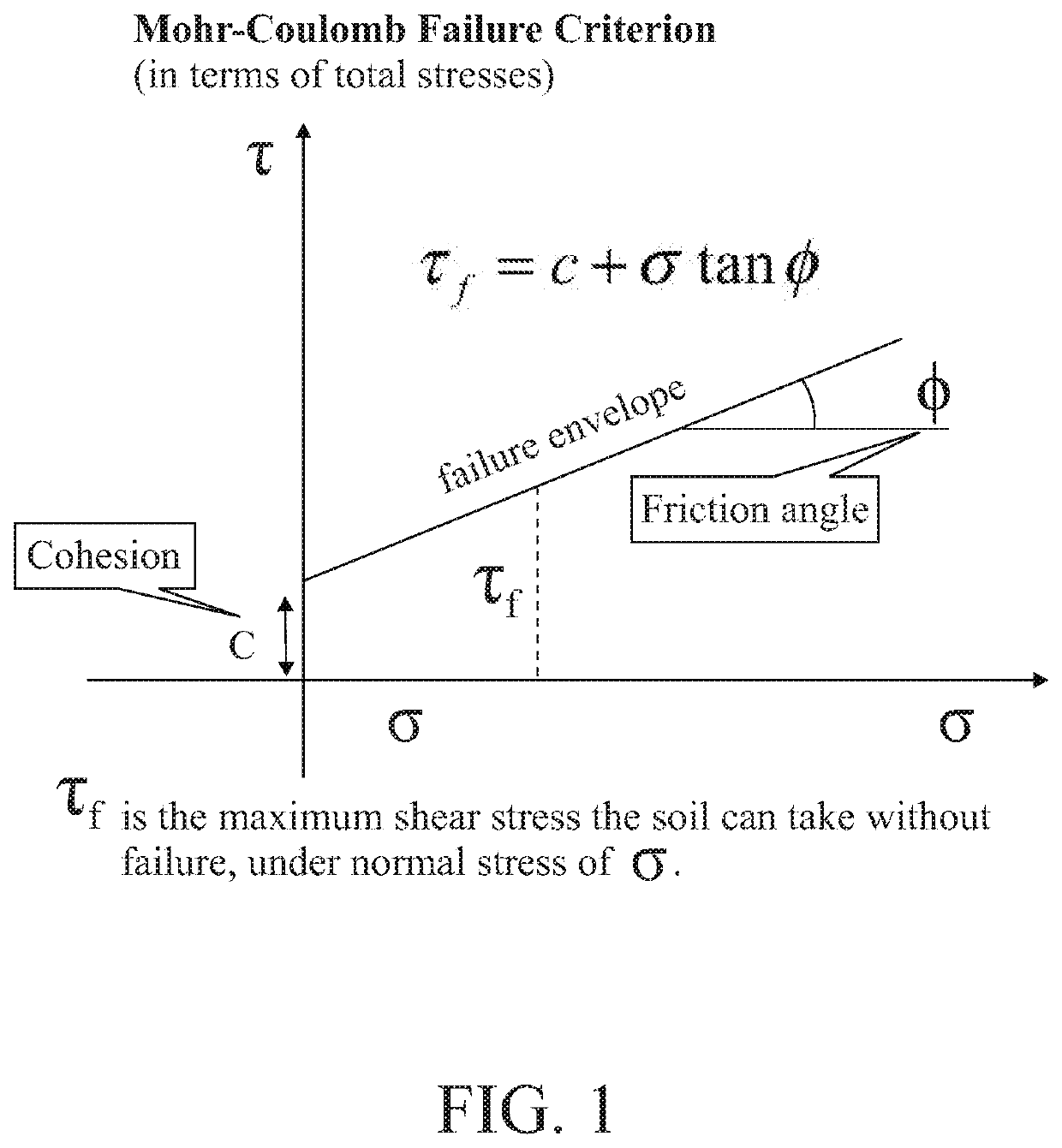
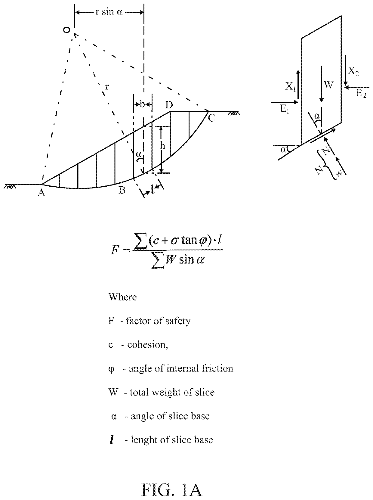
[0001]This application claims the priority from PCT application PCT / US2017 / 029392, filed Apr. 25, 2017, entitled Portable Device for Direct Shear Express Field Test and U.S. Provisional Patent Application Ser. No. 62 / 326,917, filed on Apr. 25, 2016, entitled Portable Device for Direct Shear Express Field Test, this prior application is herewith incorporated by reference in its entirety.BACKGROUND OF THE INVENTION[0002]Engineers frequently need to test physical soil parameters in order to calculate slope stability. Existing devices apply a vertical load, then find maximum corresponding horizontal load which causes failure. By changing a load acting upon the sample and plotting points of normal stress σ (Sigma), shear stress τ (Tau), and drawing a failure envelope line through them—cohesion and angle of internal friction may be determined—using the Mohr-Coulomb formula, as described in ASTM D 3080-98. (ASTM Designation: D 3080-98 entitled “Standard Test Method for Direct Shear Test of...

Claims


Application Information

Patent Timeline
Patent Type & Authority Patents(United States)
IPC IPC(8): G01N3/24G01N33/24E02D1/00E02D1/02
CPCG01N3/24E02D1/00E02D1/02E02D1/022G01N33/24G01N2203/0019G01N2203/0284
Inventor BELFER, BORIS S.
Owner SCHWARTZ ROBERT M
Learn More