
Vibration damping device of inverted structure

a technology of vibration damping and inverted structure, which is applied in the direction of liquid based dampers, shock absorbers, mechanical instruments, etc., can solve the problems of increasing the frictional force generated by the vibration damping device, the reaction of the rod also increases, and the rod is easily distorted. to achieve the effect of reducing the frictional property

Active Publication Date: 2021-04-27
HONDA MOTOR CO LTD
View PDF9 Cites 1 Cited by
  • Summary
  • Abstract
  • Description
  • Claims
  • Application Information

AI Technical Summary

Benefits of technology

The present inventors found a way to reduce the friction of a vibration damping device used in an inverted structure. By reducing wear of the bearing section, they were able to significantly lower the frictional force. This invention provides a vibration damping device with lower friction properties.

Problems solved by technology

Therefore, the rod is easily distorted.
However, if a rod diameter is increased to improve the rigidity of the rod, a frictional force generated in the vibration damping device increases and the reaction of the rod also increases.
Accordingly, when the vibration damping device having the large rod diameter is applied for example to a damper of a vehicle or the like, riding comfort of the vehicle or the like is deteriorated because, for example, thrust from the damper increases.
Therefore, it is difficult to achieve both of the damping property and the rigidity of the vibration damping device of the upright structure.
Further, since the vibration damping device of the inverted structure is limited to a monotube type, a repulsion force of a gas chamber increases compared with a vibration damping device of a twin-tube type.
When the vibration damping device is applied for example as a damper of a vehicle or the like, the increase in the repulsion force tends to be a cause of easy fluctuation in a vehicle height due to the influence of temperature.
However, friction is not considered to be sufficiently reduced in the vibration damping device of the inverted structure in which a frictional force easily increases.

Method used


Image

  • Vibration damping device of inverted structure
  • Vibration damping device of inverted structure
  • Vibration damping device of inverted structure

Examples


example 1

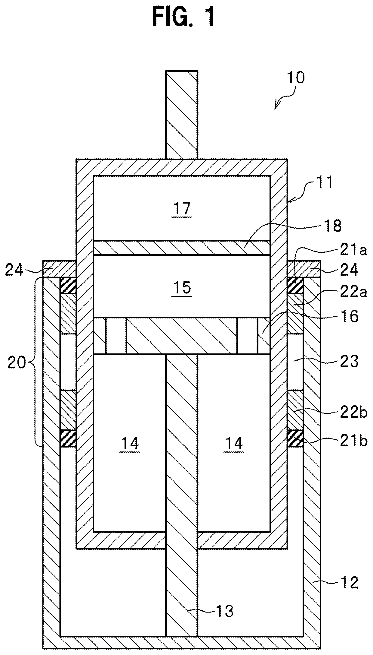
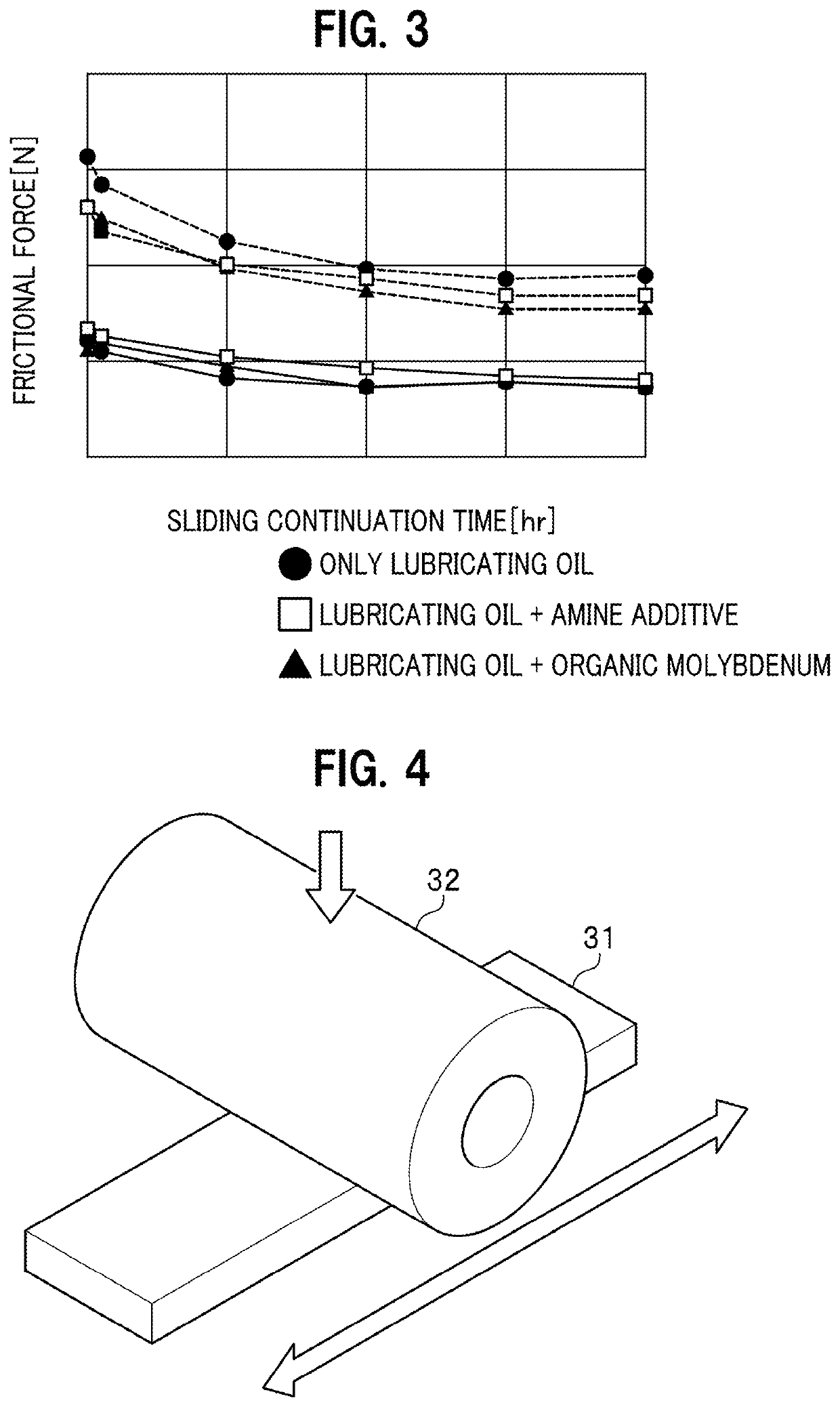
[0079]Example 1 is a vibration damping device of an inverted structure in which a bush containing 85 mass % of polytetrafluoroethylene and 15 mass % of perfluoro alkoxy alkane (PFA) is used as a bush and oil obtained by adding 1000 ppm of molybdenum dithiocarbamate (MoDTC) to the existing damper oil is used as lubricating oil.

[0080]The bush was formed in a substantially cylindrical shape. The inner diameter of the bush was 40 mm, the outer diameter of the bush was 44 mm, and the height of the bush was 20 mm. The distance between bushes of the vibration damping device was 115 mm.


PUM

PropertyMeasurementUnit
frequencyaaaaaaaaaa
frictional forceaaaaaaaaaa

Abstract

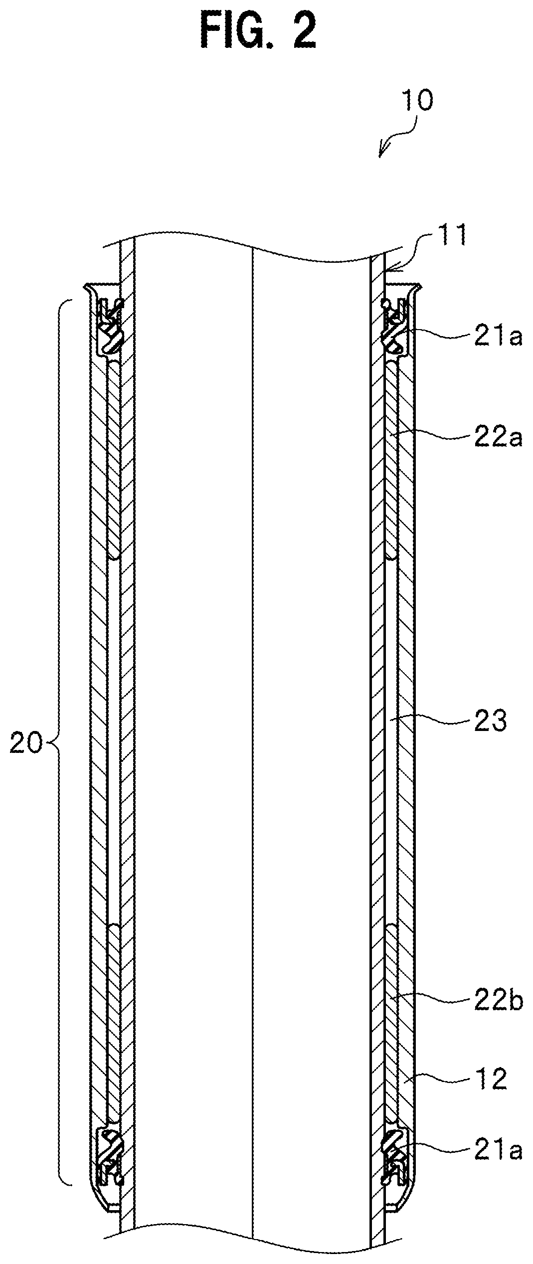
A vibration damping device of an inverted structure includes a cylinder, a rod capable of protruding and retracting in the cylinder, an outer cylinder coupled to the rod and inserted over the outer periphery of the cylinder, and a bush slidably inserted between the outer cylinder and the cylinder. A gap between the outer cylinder and the cylinder is filled with lubricating oil. The bush contains polytetrafluoroethylene and perfluoro alkoxy alkane. The lubricating oil contains an organic molybdenum additive.

Description

BACKGROUND OF THE INVENTION1. Field of the Invention[0001]The present invention relates to a vibration damping device of an inverted structure.2. Description of the Related Art[0002]In a vibration damping device (a damping device) of an upright structure in the past, a rod reciprocating in a cylinder of the vibration damping device receives a lateral force applied to the vibration damping device. Therefore, the rod is easily distorted. However, if a rod diameter is increased to improve the rigidity of the rod, a frictional force generated in the vibration damping device increases and the reaction of the rod also increases. Accordingly, when the vibration damping device having the large rod diameter is applied for example to a damper of a vehicle or the like, riding comfort of the vehicle or the like is deteriorated because, for example, thrust from the damper increases. Therefore, it is difficult to achieve both of the damping property and the rigidity of the vibration damping devic...

Claims


Application Information

Patent Timeline
Patent Type & Authority Patents(United States)
IPC IPC(8): F16F9/36F16F9/18F16F9/32F16F9/06
CPCF16F9/18F16F9/064F16F9/3235F16F9/366F16F2222/12F16F2224/02F16F2224/04F16F2232/08F16F2234/02F16F9/19F16F9/3278F16F2230/04
Inventor SOGAWA, NAOKIKOMORI, KENTAROFUJIMOTO, GAKUYO
Owner HONDA MOTOR CO LTD
Learn More