
Detection of the direction of rotation of a vehicle engine

a technology of vehicle engine and rotation direction, which is applied in the direction of electric control, machines/engines, fuel injection control, etc., can solve the problems of engine bouncing back, engine crashing, engine crashing, etc., and achieve the effect of limiting the risk of damage to the flywheel of the engine and limiting the reverse rotation of the engin

Active Publication Date: 2021-03-23
VITESCO TECH GERMANY GMBH
View PDF4 Cites 0 Cited by
  • Summary
  • Abstract
  • Description
  • Claims
  • Application Information

AI Technical Summary

Benefits of technology

The invention proposes a simple and reliable method for determining the direction of rotation of the crankshaft of a motor vehicle engine, without injecting fuel into the cylinders. This method helps prevent damage to the engine's flywheels and limits the level of pollution caused by a reverse rotation of the engine.

Problems solved by technology

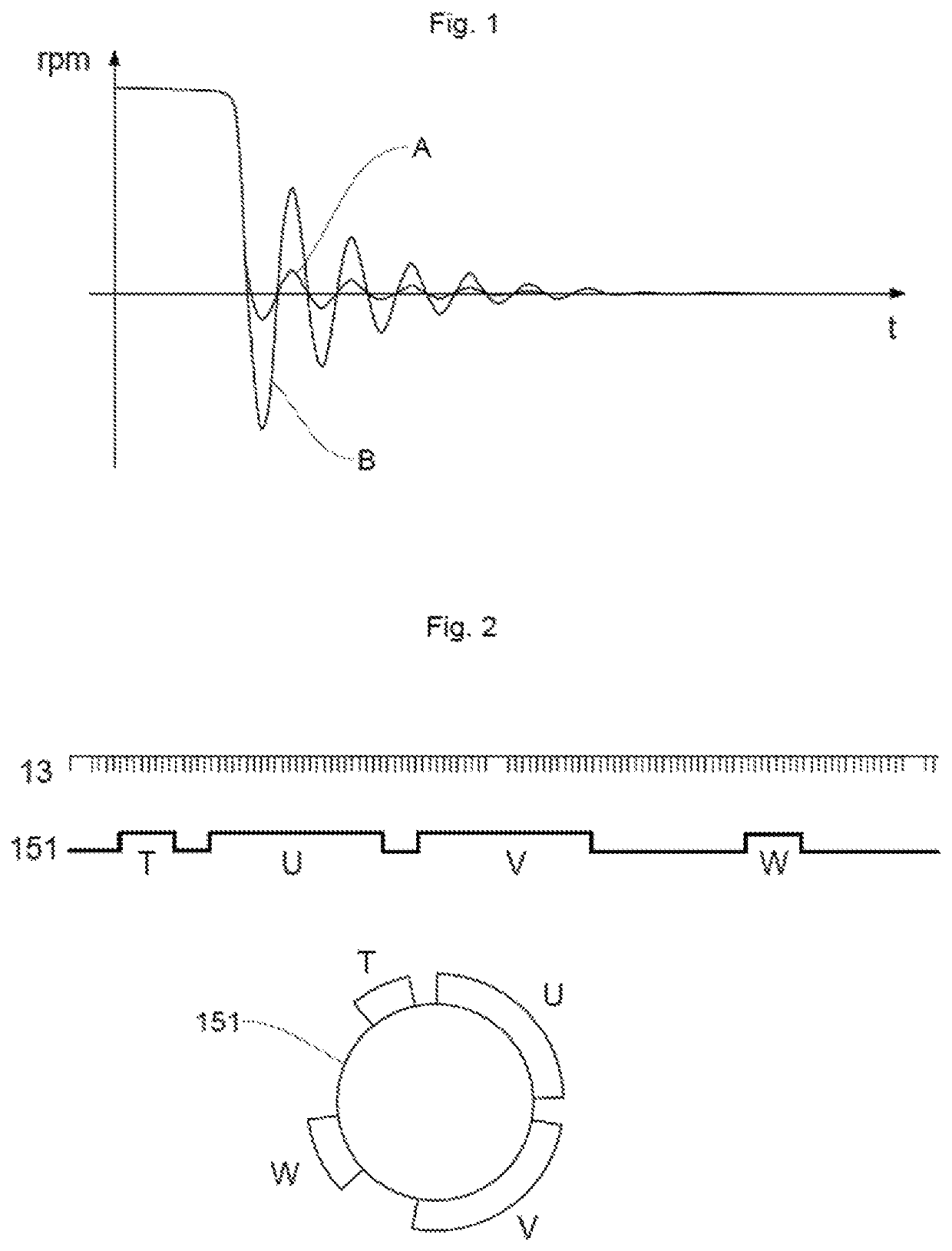
If the torque generated by the combustion of the fuel is not sufficient to start the engine, the latter stalls, causing the engine to bounce back.
Specifically, since the rotating flywheels have stored kinetic energy, the abrupt stopping of the engine does not allow them to dissipate the stored energy, thus causing the bounce-back effect.
Such a reversal in the direction of rotation of the elements of an engine can cause damage to the flywheels connected to the crankshaft and thus cause the engine to break down.
However, such a sensor is expensive and requires particular technology, which is not appropriate for all vehicle engines.
However, such a camshaft sensor is expensive and, as a result, is not installed as standard on an engine.
Moreover, when such a camshaft sensor is present, it may be defective.
Thus, if the camshaft sensor is absent or defective and there is no bidirectional crankshaft sensor, the direction of rotation of the engine elements cannot be determined, and this represents a drawback.

Method used


Image

  • Detection of the direction of rotation of a vehicle engine
  • Detection of the direction of rotation of a vehicle engine
  • Detection of the direction of rotation of a vehicle engine

Examples


Embodiment Construction

[0059]The invention will be presented below for the purpose of implementation in a motor vehicle. However, any implementation in a different context, in particular for any vehicle comprising a combustion engine of which it is necessary to determine the direction of rotation is also targeted by the present invention.

[0060]1 / System 1

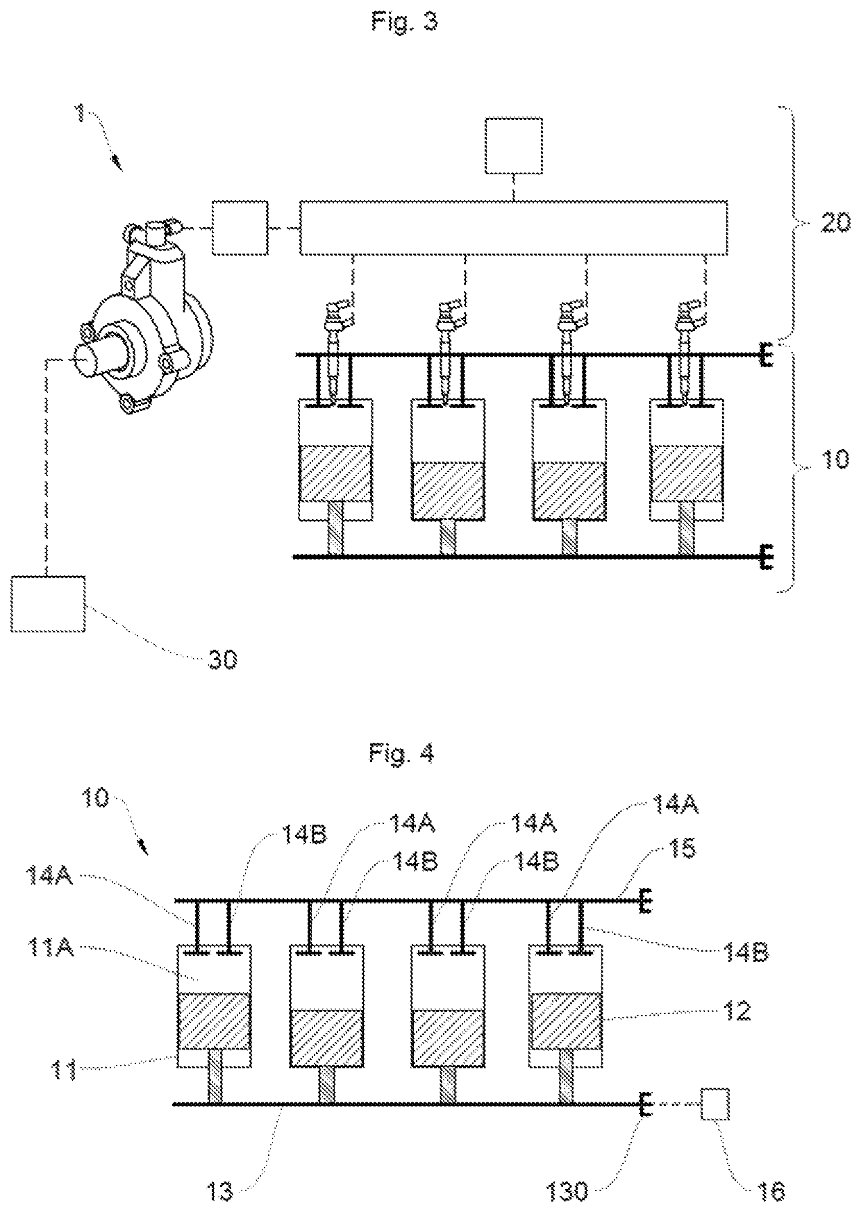
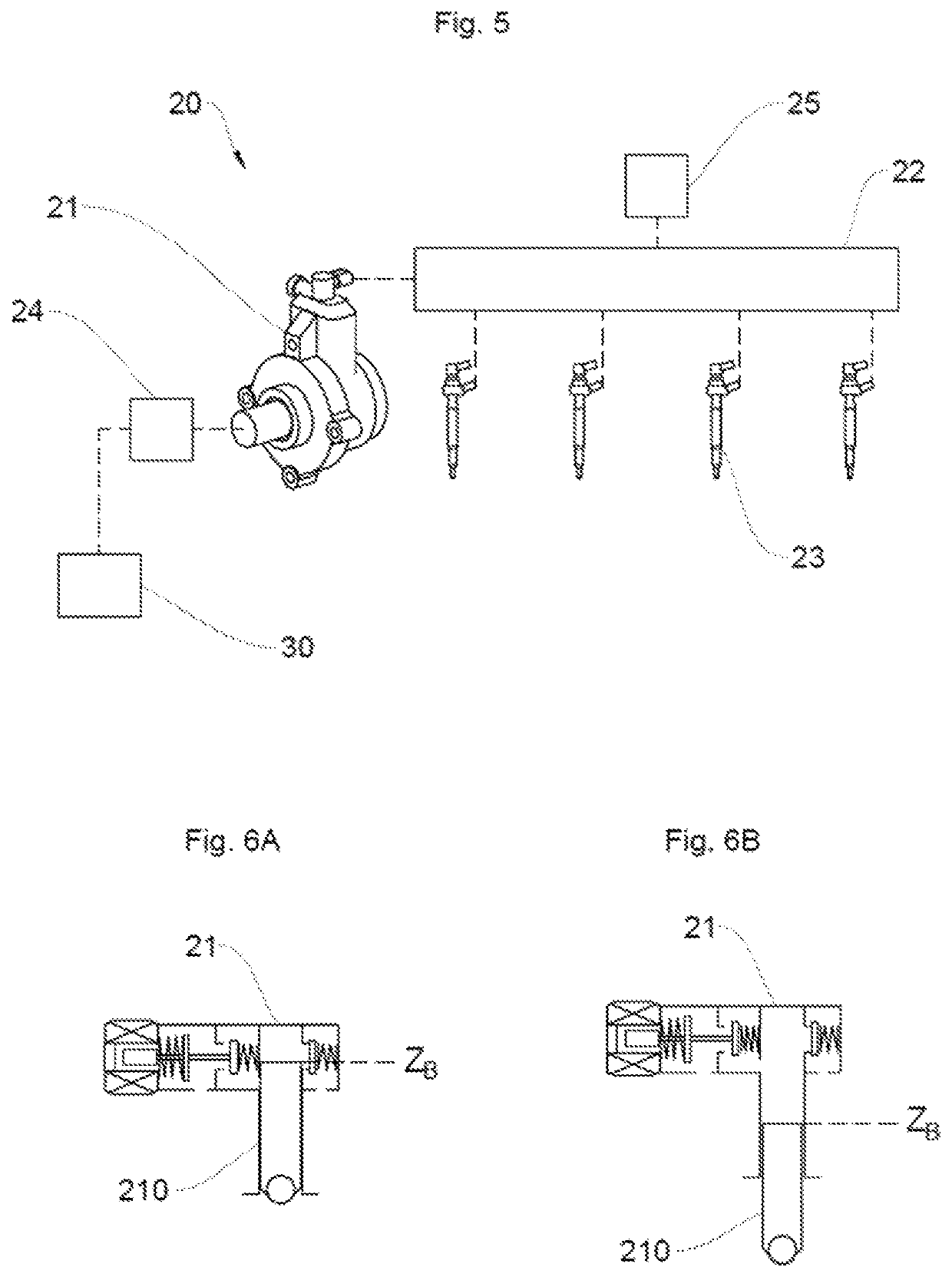
[0061]With reference to FIG. 3, the system 1, according to one embodiment of the invention, comprises a motor vehicle combustion engine 10, an injection module 20 and a control module 30 of the injection module 20.

[0062]a. Engine 10

[0063]As shown schematically in FIG. 4, the combustion engine 10 comprises, in a known way, a plurality of cylinders 11 that each delimit a combustion chamber 11A in which a piston 12 slides, the movement of which is driven by compression and expansion of the gases resulting from the compression of a fuel-air mixture introduced into the combustion chambers 11A.

[0064]As a reminder, the air and the gases are introduced and expelle...


PUM


Abstract

Disclosed is a method for detecting the direction of rotation of a crankshaft of an engine of a motor vehicle. The detection method includes in particular, when the crankshaft is in a second predetermined angular position between a low angular position and a high angular position of the crankshaft, a step of commanding the closure of a control valve for the intake of fuel into the high-pressure pump, a step of measuring a second pressure value in the high-pressure rail, and a step of detecting a nominal direction of rotation of the crankshaft if the second pressure value measured is greater than or equal to an expected pressure value or of detecting a reverse direction of rotation of the crankshaft if the second pressure value measured is less than the expected pressure value.

Description

BACKGROUND OF THE INVENTIONField of the Invention[0001]The invention relates to the field of the rotation of a combustion engine and concerns more precisely a method and a system for detecting the direction of rotation of a combustion engine in order to limit the injection of fuel into the cylinders of the engine when the engine is rotating in a reverse direction.[0002]The invention aims in particular to detect the direction of rotation of a combustion engine of a vehicle by detecting the direction of rotation of the crankshaft of said engine, when such a crankshaft is not equipped with a bidirectional position sensor and the position sensor of the camshaft is defective or does not exist. The invention aims notably to limit the risks of damage to the flywheels of the engine.Description of the Related Art[0003]As is known, a combustion engine of a motor vehicle has hollow cylinders that each delimit a combustion chamber into which a fuel-air mixture is injected. This mixture is compr...

Claims


Application Information

Patent Timeline
Patent Type & Authority Patents(United States)
IPC IPC(8): F02D41/38F02D41/00F02D41/06
CPCF02D41/009F02D41/3845F02D41/062F02D2200/0604F02D2200/0614F02D2250/06F02D41/22F02D2041/0092F02D2041/0095F02D2200/0602
Inventor AGNUS, YVESLEFEVRE, JULIEN
Owner VITESCO TECH GERMANY GMBH
Learn More