
Robot hand apparatus, robot hand system, and holding method

a robot hand and hand technology, applied in the field of robot hand apparatus, can solve the problem that the position of the robot hand apparatus cannot be freely determined, and achieve the effect of reliably holding and easy picking up

Active Publication Date: 2021-03-16
PANASONIC INTELLECTUAL PROPERTY MANAGEMENT CO LTD
View PDF5 Cites 2 Cited by
  • Summary
  • Abstract
  • Description
  • Claims
  • Application Information

AI Technical Summary

Benefits of technology

The patent describes a robot hand system that can easily pick up objects placed in narrow spaces and hold them securely even when an external force is applied. This technology provides a reliable and efficient solution for efficiently handling objects, particularly in situations where space is limited.

Problems solved by technology

However, in the narrow space like the inside of the storage shelf or the inside of the package box described above, a hand may interfere with the storage shelf or the package box, and thus the sucking position of the robot hand apparatus cannot be freely determined, or the object cannot be picked up because the sucking position of the robot hand apparatus cannot be freely determined or the posture of the robot hand apparatus cannot be freely changed.

Method used


Image

  • Robot hand apparatus, robot hand system, and holding method
  • Robot hand apparatus, robot hand system, and holding method
  • Robot hand apparatus, robot hand system, and holding method

Examples


first embodiment

1-1. Configuration of Robot Hand System

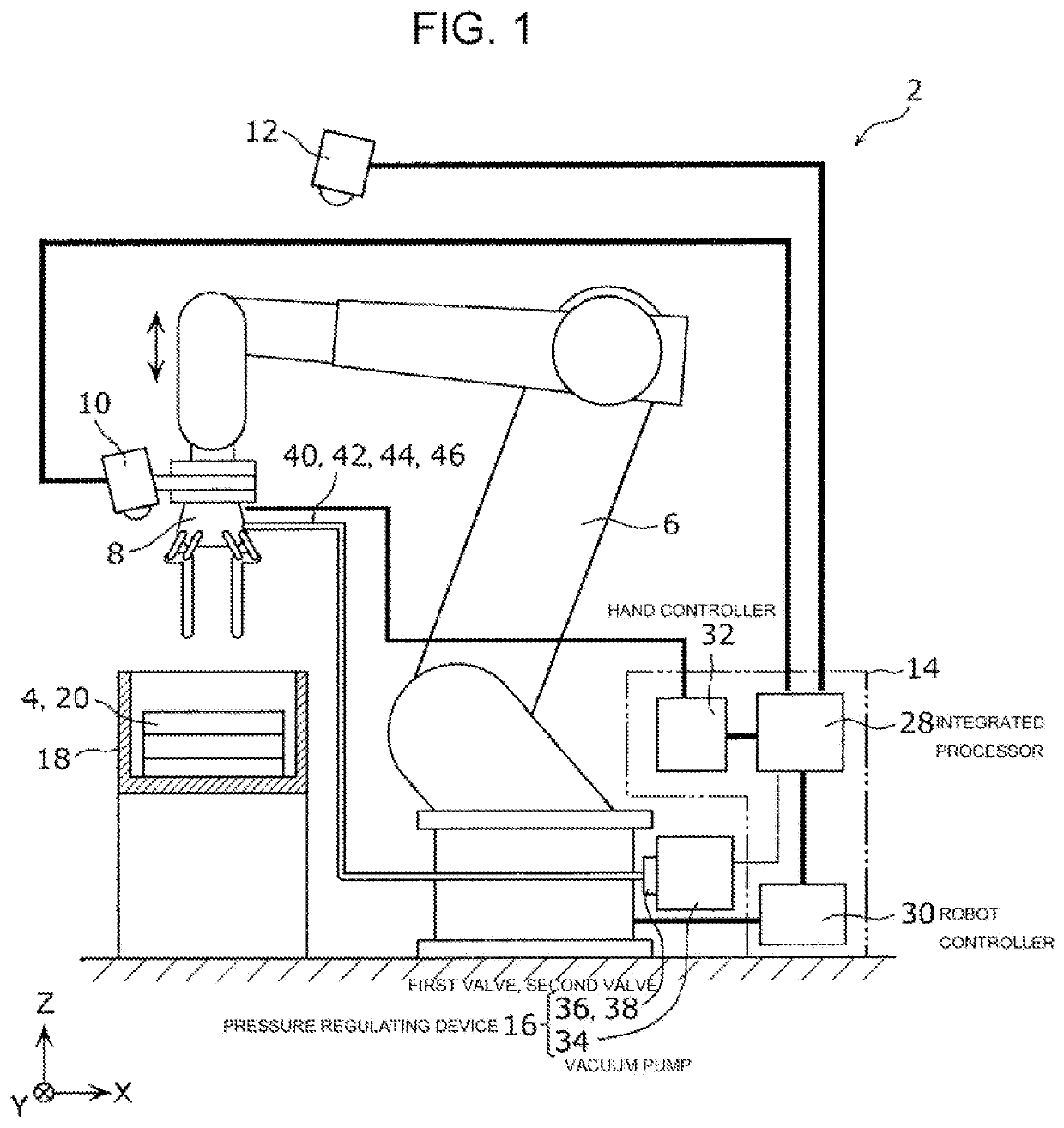
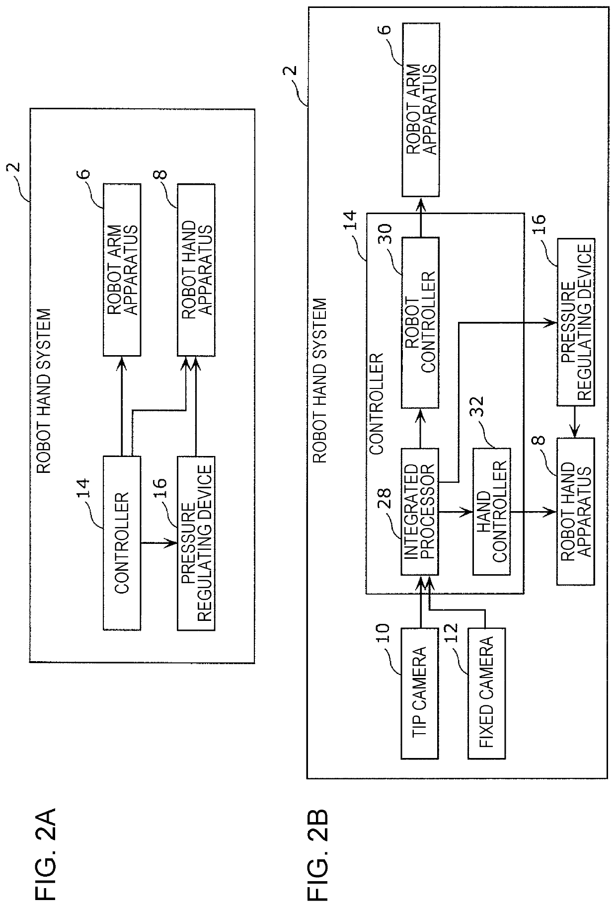
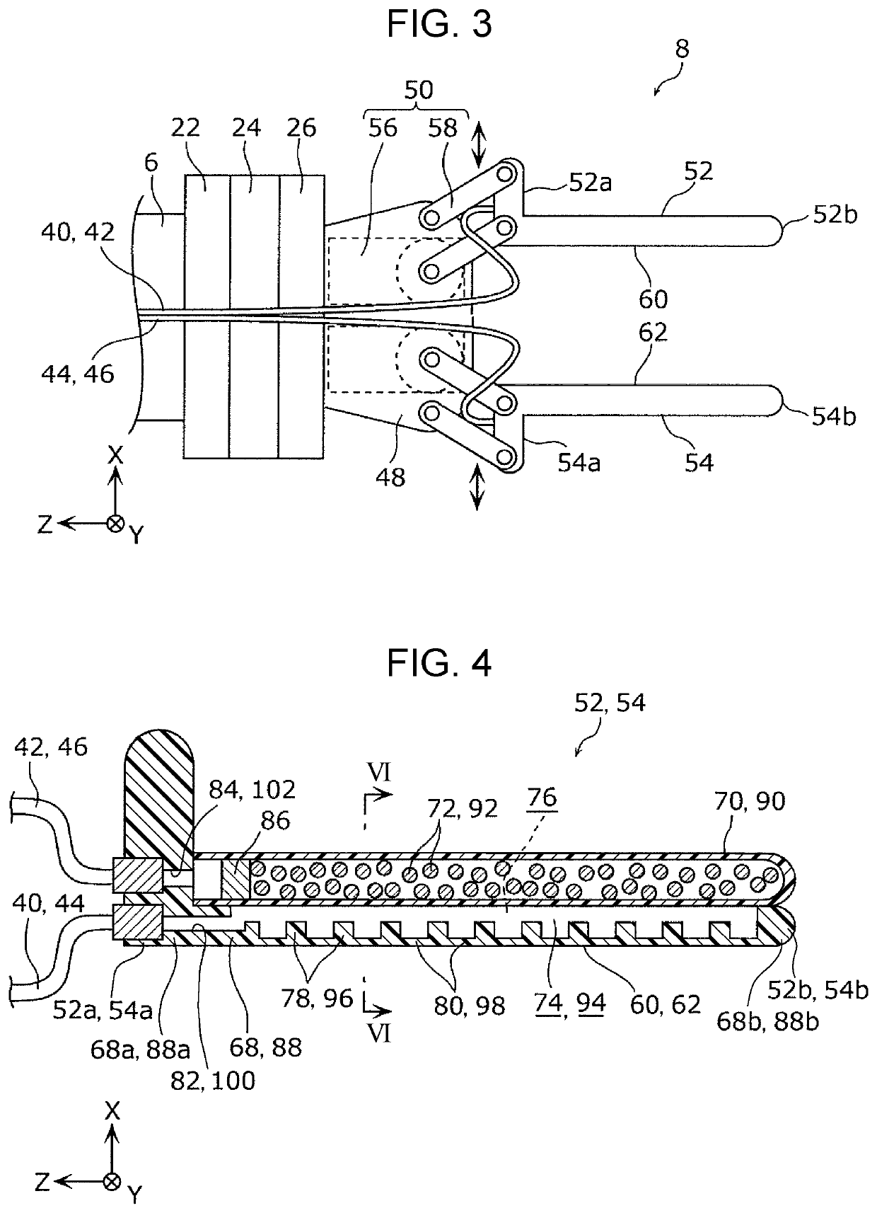
[0063]A configuration of a robot hand system 2 according to a first embodiment is described first with reference to FIGS. 1 to 3. FIG. 1 illustrates the configuration of the robot hand system 2 according to the first embodiment. FIG. 2A is a block diagram illustrating a major functional configuration of the robot hand system 2 according to the first embodiment. FIG. 2B is a block diagram illustrating a specific functional configuration of the robot hand system 2 according to the first embodiment. FIG. 3 illustrates a robot hand apparatus 8 in an enlarged manner according to the first embodiment.

[0064]The robot hand system 2 according to the first embodiment is a system that picks up and conveys an object 4. As illustrated in FIGS. 1, 2A, and 2B, the robot hand system 2 includes a robot arm apparatus 6, the robot hand apparatus 8, a tip camera 10, a fixed camera 12, a controller 14, and a pressure regulating device 16.

[0065]The object 4 is, for ...

second embodiment

2-1. Configuration of Robot Hand Apparatus

[0133]A configuration of a robot hand apparatus 8A according to a second embodiment is described next with reference to FIGS. 13 and 14. FIG. 13 partly illustrates a robot hand system 2A according to the second embodiment. FIG. 14 is a cross-sectional view illustrating a first holder 52A (second holder 54A) of the robot hand apparatus 8A according to the second embodiment. FIG. 13 does not illustrate the tip camera 10, the fixed camera 12, the controller 14, and the pressure regulating device 16 for the convenience of the description. In this embodiment, the same reference signs are applied to the same components as those of the first embodiment, and the redundant description thereof is omitted.

[0134]As illustrated in FIG. 13, in the robot hand system 2A according to the second embodiment, the configurations of the first holder 52A and the second holder 54A of the robot hand apparatus 8A differ from those of the first embodiment. Specificall...


PUM


Abstract

A robot hand apparatus includes a first holder having a first sucking surface that is bendable at any position and configured to suck an object using negative pressure; a second holder arranged to oppose the first sucking surface of the first holder; and a driving mechanism configured to change a distance between the first holder and the second holder to sandwich the object between the first holder and the second holder.

Description

BACKGROUND1. Technical Field[0001]The present disclosure relates to a robot hand apparatus, a robot hand system, and a holding method.2. Description of the Related Art[0002]A robot hand apparatus of a type having a function of sucking an object using negative pressure and a function of sandwiching the object is known as one of robot hand apparatuses that hold objects (see, Japanese Patent No. 5957295 and Japanese Unexamined Patent Application Publication No. 2014-200874).[0003]The robot hand apparatus disclosed in Japanese Patent No. 5957295 includes a pair of hands that sandwich an object. The pair of hands each have a sucking surface having sucking pads. An object is sucked to the sucking pads of the hand using negative pressure, and thus the object can be held by only one hand. Moreover, the state can be transitioned from a state in which the object is sucked to and held by one hand to a state in which the object is sandwiched by the pair of hands while the held state is maintain...

Claims


Application Information

Patent Timeline
Patent Type & Authority Patents(United States)
IPC IPC(8): B25J15/06B25J15/00B25J15/02B25J15/12B25J9/16
CPCB25J15/065B25J9/1612B25J9/1697B25J15/0023B25J15/0038B25J15/0253B25J15/0616B25J15/12G05B2219/40053B25J13/00B25J13/08B25J15/00
Inventor NAGATA, TAKAYUKIOKAZAKI, YASUNAOASAI, KATSUHIKOINOUE, KAZUO
Owner PANASONIC INTELLECTUAL PROPERTY MANAGEMENT CO LTD
Learn More