Determining wheel slippage on self driving vehicle

a self-driving vehicle and slippage technology, applied in process and machine control, instruments, navigation instruments, etc., can solve problems such as loss of traction, and achieve the effect of reducing the maximum driving speed

Active Publication Date: 2021-03-09
WAYMO LLC
View PDF27 Cites 0 Cited by
  • Summary
  • Abstract
  • Description
  • Claims
  • Application Information

AI Technical Summary

Benefits of technology

[0012]In one scenario, the corrective driving action may include the deceleration subsystem performing at least one of a selected braking technique or a selected braking pattern. Or the corrective driving action may include adjusting at least one of a braking profile or a desired stopping point for the vehicle. Or the corrective driving action may include reducing a maximum driving speed along a selected portion of roadway.

Problems solved by technology

A loss of traction may be due to various environmental conditions, such as ice, snow or puddles on the road surface.

Method used


Image

  • Determining wheel slippage on self driving vehicle
  • Determining wheel slippage on self driving vehicle
  • Determining wheel slippage on self driving vehicle

Examples


example vehicle

Systems

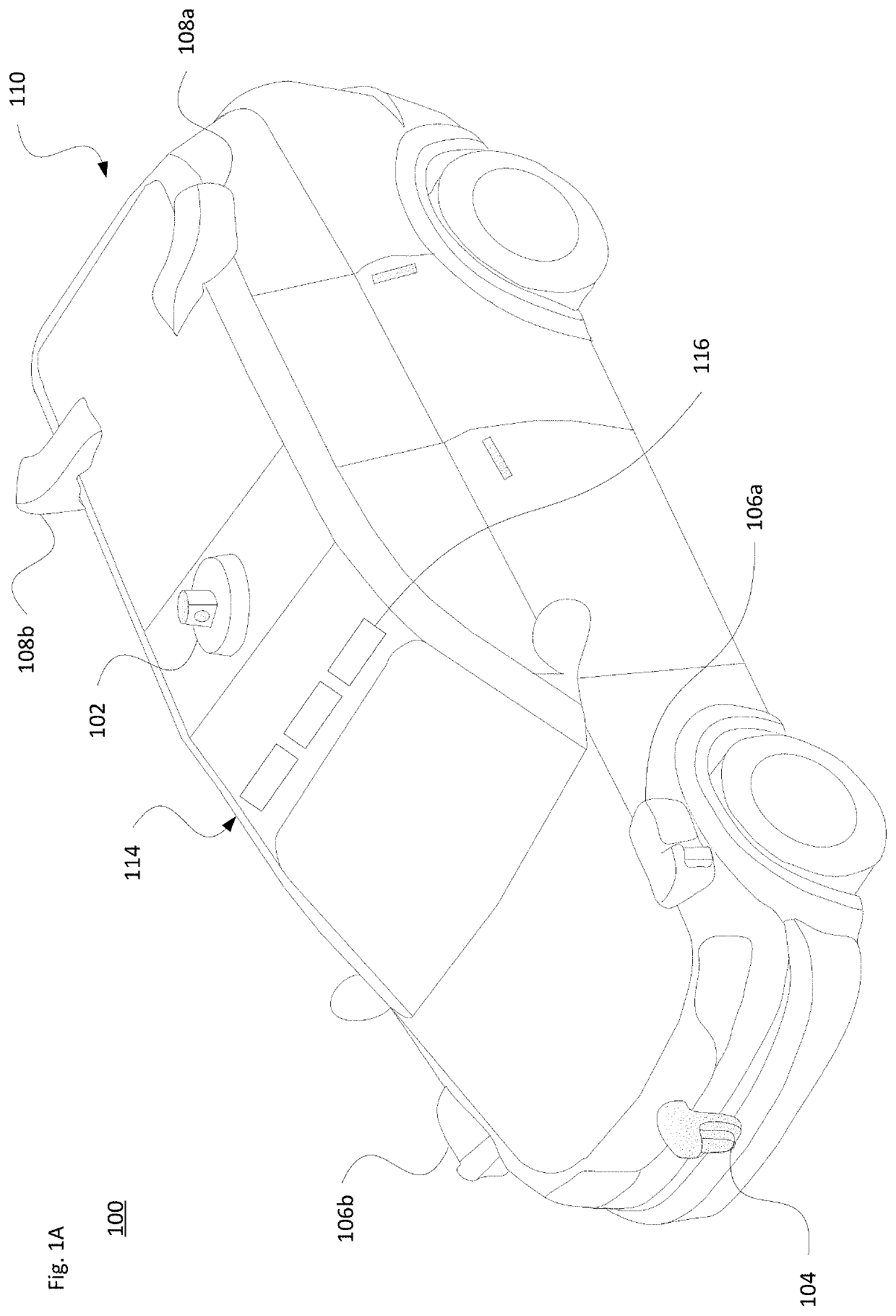
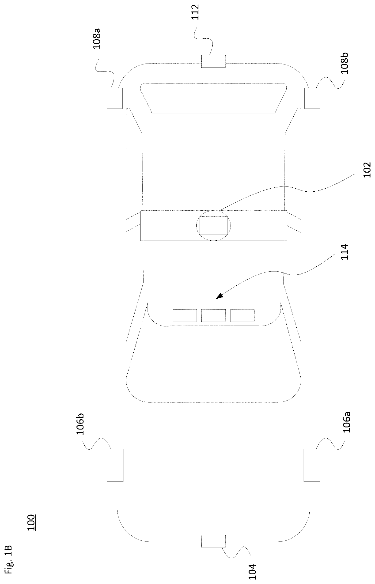
[0033]FIG. 1A illustrates a perspective view of an example passenger vehicle 100, such as a minivan, sport utility vehicle (SUV) or other vehicle. FIG. 1B illustrates a top-down view of the passenger vehicle 100. The passenger vehicle 100 may include various sensors for obtaining information about the vehicle's external environment. For instance, a roof-top housing 102 may include a Lidar sensor as well as various cameras, radar units, infrared and / or acoustical sensors. Housing 104, located at the front end of vehicle 100, and housings 106a, 106b on the driver's and passenger's sides of the vehicle may each incorporate Lidar, radar, camera and / or other sensors. For example, housing 106a may be located in front of the driver's side door along a quarter panel of the vehicle. As shown, the passenger vehicle 100 also includes housings 108a, 108b for radar units, Lidar and / or cameras also located towards the rear roof portion of the vehicle. Additional Lidar, radar units and / or c...

example implementations

[0060]In view of the structures and configurations described above and illustrated in the figures, various aspects will now be described in accordance with aspects of the technology.

[0061]FIG. 4 illustrates a scenario in which vehicle 400 uses sensors 402 and 404 to detect the presence of another vehicle 406. As shown, sensors 402 and 404 have respective fields of view (FOV) 408 and 410 to detect objects in front of vehicle 400. In this example, the sensors 402 and 404 may be, e.g., Lidar, radar, image and / or acoustical sensors.

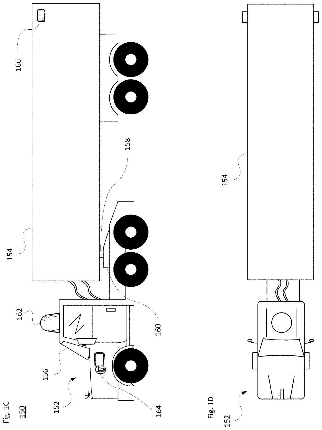
[0062]Various sensors may be located at different places around the vehicle (see FIGS. 1A-D) to gather data from different parts of the external environment. Certain sensors may have different fields of view depending on their placement around the vehicle and the type of information they are designed to gather. For instance, different Lidar sensors may be used for near (short range) detection of objects adjacent to the vehicle (e.g., less than 2-10 meters), w...


PUM


Abstract

The technology relates to determining the current state of friction that a vehicle's wheels have with the road surface. This may be done via active or passive testing or other monitoring while the vehicles operates in an autonomous mode. In response to detecting the loss of traction, the vehicle's control system is able to use the resultant information to select an appropriate braking level or braking strategy. This may be done for both immediate driving operations and planning future portions of an ongoing trip. For instance, the on-board system is able to evaluate appropriate conditions and situations for active testing or passive evaluation of traction through autonomous braking and / or acceleration operations. The on-board computer system may share slippage and other road condition information with nearby vehicles and with remote assistance, so that it may be employed with broader fleet planning operations.

Description

CROSS-REFERENCE TO RELATED APPLICATIONS[0001]This application is related to U.S. application Ser. No. 16 / 217,235, entitled Detecting General Road Weather Conditions, filed concurrently herewith, the entire disclosure of which is incorporated by reference herein.BACKGROUND[0002]Autonomous vehicles, such as vehicles that do not require a human driver, can be used to aid in the transport of passengers or cargo from one location to another. Such vehicles may operate in a fully autonomous mode or a partially autonomous mode where a person may provide some driving input. In order to operate in an autonomous mode, the vehicle may employ various on-board sensors to detect features of the external environment, and use received sensor information to perform various driving operations. However, if the wheels lose traction with the road surface, this may adversely impact the driving capabilities of the vehicle. Slippage may occur as a result of various environmental factors, and the sensors arr...

Claims


Application Information

Patent Timeline
Patent Type & Authority Patents(United States)
IPC IPC(8): B60W30/02G05D1/00G05D1/02B60W10/04B60W10/18B60W10/20G01S17/86G01S17/931
CPCB60W30/02B60W10/04B60W10/18B60W10/20G05D1/0088G05D1/0291B60W2300/12B60W2300/145B60W2420/42B60W2420/52B60W2552/00G01S17/86G01S17/931G05D2201/0213B60W40/068B60W60/001B60W2720/10B60W2556/45B60W2556/65G01C21/3415G01C21/3461B60W30/18172B60W2050/0031B60W30/14B60W40/02B60W30/10B60W40/105B60W2520/04B60W2520/10
Inventor SILVER, DAVID HARRISONGUTMANN, JENS-STEFFEN RALFJAMES, MICHAEL
Owner WAYMO LLC
Why Eureka
Try Eureka