
Acidic gas recovery system and reclaiming device to be used in same

a gas recovery system and acid gas technology, applied in the direction of separation process, dispersed particle separation, chemistry apparatus and processes, etc., can solve the problems of inhibiting the absorption performance of the absorption liquid by coexisting materials, oxidative degradation of amine by oxygen in the exhaust gas, etc., to achieve the effect of stably preventing and easy separation of non-volatile materials

Active Publication Date: 2021-03-09
MITSUBISHI HEAVY IND ENG LTD
View PDF11 Cites 0 Cited by
  • Summary
  • Abstract
  • Description
  • Claims
  • Application Information

AI Technical Summary

Benefits of technology

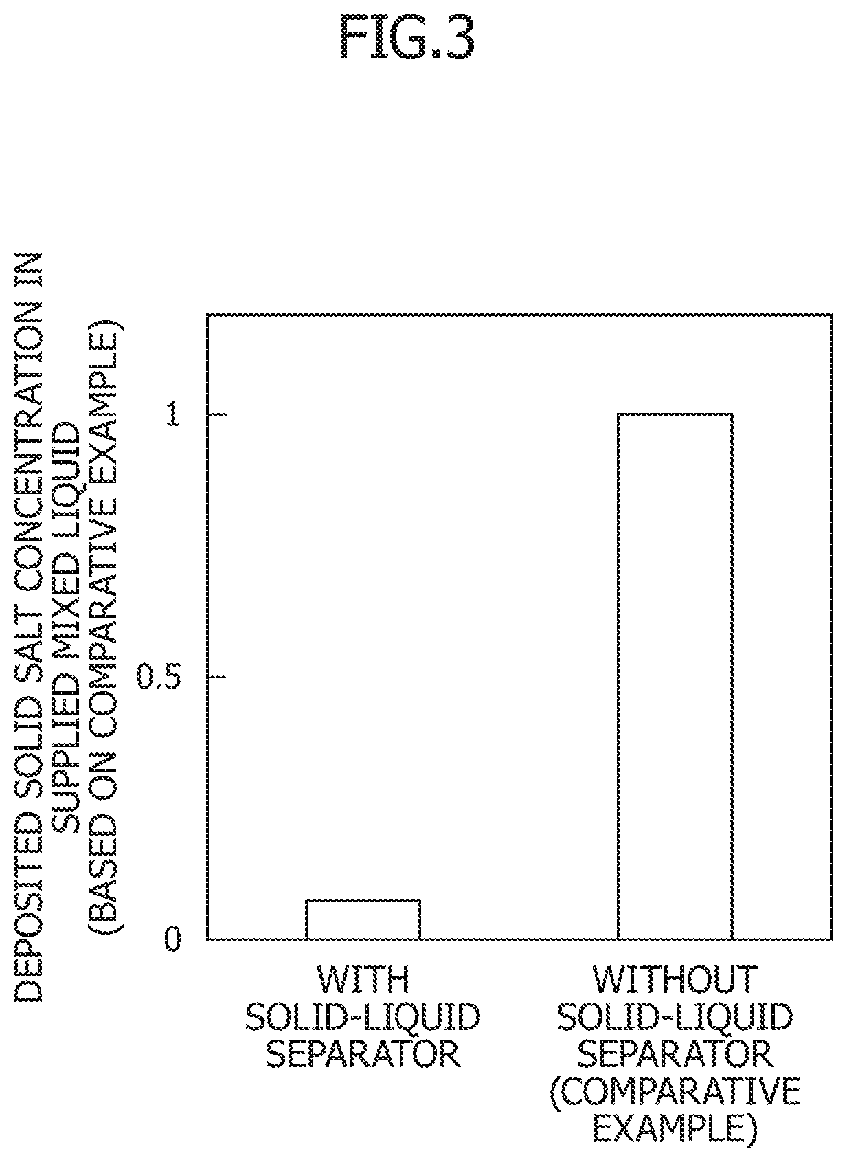
The present invention provides a method for separating non-volatile materials from a vaporized material containing amine. This is achieved by heating the absorption liquid in a gas-liquid separator without mixing it with an alkaline agent, which makes it easier to separate the non-volatile materials from the vaporized material. The recovered vaporized material is then reintroduced into the gas-liquid separator to recover the original amine. This method prevents the vaporized material from entraining components in the gas-liquid separator due to liquid entrainment. Further, a solid-liquid separator is provided to remove the deposited solids formed due to addition of the alkaline agent and to supply a more stable vaporized material for recovery.

Problems solved by technology

However, this cyclic use may cause oxidative degradation of amine by oxygen in the exhaust gas, formation of amine nitrates and amine sulfates by absorption of residual NOx and residual SOx in the exhaust gas with amine, and inflow of solids such as soot and dust contained in the exhaust gas.
These coexisting materials inhibit an absorbing performance of the absorption liquid.

Method used


Image

  • Acidic gas recovery system and reclaiming device to be used in same
  • Acidic gas recovery system and reclaiming device to be used in same
  • Acidic gas recovery system and reclaiming device to be used in same

Examples


first embodiment

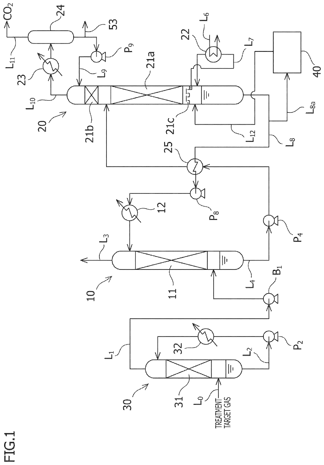
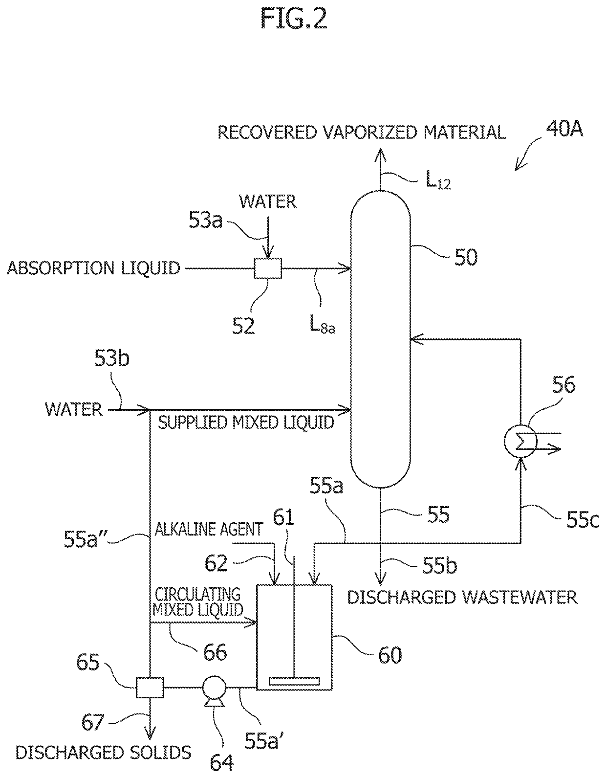
[0035]As shown in FIG. 1, an acidic gas recovery system of this embodiment at least includes: an absorption column 10 configured to bring a treatment target gas containing CO2 as an acidic gas and an amine absorption liquid as an absorption liquid for absorbing the acidic gas into gas-liquid contact so as to remove CO2 from the treatment target gas by causing the amine absorption liquid to absorb CO2; a regeneration column 20 configured to cause the amine absorption liquid having absorbed CO2 (a rich absorption liquid) to release CO2 so as to regenerate the amine absorption liquid (a lean absorption liquid) after releasing CO2 as the absorption liquid for CO2; and a reclaiming device 40 configured to separate the amine absorption liquid subjected to cyclic use as described above from coexisting materials other than an absorbent. A detailed configuration of the reclaiming device 40 of this embodiment is illustrated as a reclaiming device 40A in FIG. 2.

[0036]This embodiment describes ...

second embodiment

[0065]As shown in FIG. 4, a reclaiming device 40B of a second embodiment is different from the reclaiming device 40A of the first embodiment mainly in that a liquid collector 57 configured to allow passage of a gas from below upward and to block passage of a liquid from above downward is provided inside the gas-liquid separator 50, that the first heater 56 is disposed on an accumulated liquid heating line 58 instead of the heating line 55c, the line 58 being configured to drain out an accumulated liquid accumulated in the liquid collector 57 and to introduce the heated accumulated liquid to a position between the introduction port for the absorption liquid of the line L8a and the liquid collector 57, and that the mixed liquid line 55a″ is provided with a second heater 68 in order to heat the mixed liquid deprived of the solids by using the solid-liquid separator 65. The same components as those in FIG. 2 are denoted by the same reference numerals, and explanations thereof will be om...

third embodiment

[0068]As shown in FIG. 5, a reclaiming device 40C of a third embodiment is different from the reclaiming device 40B of the second embodiment mainly in that a second heater 71 is disposed on the water line 53b instead of the mixed liquid line 55a″, the water line 53b being configured to supply the water to the gas-liquid separator 50. The same components as those in FIG. 4 are denoted by the same reference numerals, and explanations thereof will be omitted herein.

[0069]According to this embodiment, since the second heater 71 is disposed on the water line 53b, the mixed liquid is not supplied to the second heater 71 in comparison with the second embodiment. For this reason, it is possible to more reliably prevent the solids from being deposited on the heater and to more reliably prevent the bumping in the second heater 71, and thus to perform an operation more stably.


PUM

PropertyMeasurementUnit
temperaturesaaaaaaaaaa
non-volatileaaaaaaaaaa

Abstract

A reclaiming device that separates an absorption liquid from a coexisting material other than an absorbent includes: a gas-liquid separator that accepts the absorption liquid to be reclaimed together with water and separates the absorption liquid into a non-volatile material and a vaporized material; a first discharged liquid line that introduces a first discharged liquid discharged from the gas-liquid separator into the gas-liquid separator at a position below an absorption liquid introduction port; a first heater, disposed on the first discharged liquid line, that heats the first discharged liquid; a second discharged liquid line that introduces a second discharged liquid discharged from the gas-liquid separator into the gas-liquid separator at a position below a first discharged liquid introduction port; and a mixing tank, disposed on the second discharged liquid line, that mixes the second discharged liquid with an alkaline agent.

Description

TECHNICAL FIELD[0001]The present invention relates to an acidic gas recovery system and to a reclaiming device to be used in the same.BACKGROUND ART[0002]Various methods of removing and recovering acidic gases such as CO2 and H2S contained in fossil fuel combustion exhaust gases and the like have heretofore been proposed. Among them, there is a method of removing and recovering an acidic gas from a combustion exhaust gas by bringing the combustion exhaust gas into contact with an amine absorption liquid such as an alkanolamine aqueous solution.[0003]The aforementioned amine absorption liquid is subjected to cyclic use in which, after the liquid absorbs the acidic gas in an absorption column, the liquid is regenerated by releasing CO2 in a regeneration column and is then used again for absorption of the acidic gas in the absorption column. However, this cyclic use may cause oxidative degradation of amine by oxygen in the exhaust gas, formation of amine nitrates and amine sulfates by ...

Claims


Application Information

Patent Timeline
Patent Type & Authority Patents(United States)
IPC IPC(8): B01D53/14B01D53/52B01D53/62B01D53/18
CPCB01D53/1425B01D53/14B01D53/1456B01D53/1468B01D53/1475B01D53/18B01D53/52B01D53/62B01D2252/20478B01D2257/304B01D2257/504B01D2258/01Y02A50/20Y02C20/40
Inventor TANAKA, HIROSHIHIRATA, TAKUYAKAMIJO, TAKASHITSUJIUCHI, TATSUYA
Owner MITSUBISHI HEAVY IND ENG LTD
Learn More