Eyecups for optics
a technology of eyecups and optics, applied in the field of optics, can solve the problems of difficult to maintain a specified switching distance that allows traditional eyecups to function, undesirable light emission from the device,
- Summary
- Abstract
- Description
- Claims
- Application Information
AI Technical Summary
Benefits of technology
Problems solved by technology
Method used
Image
Examples
Embodiment Construction
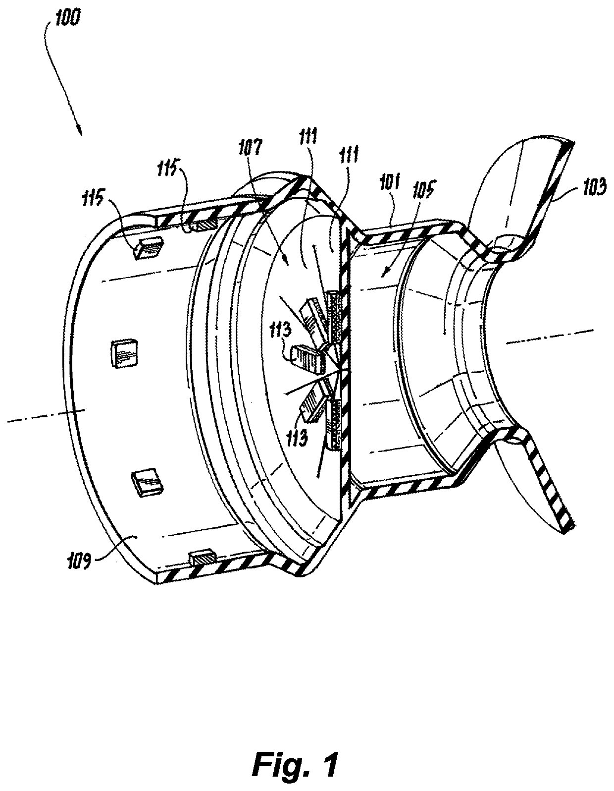
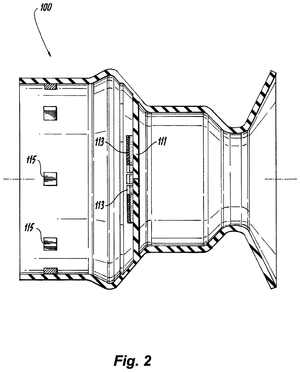
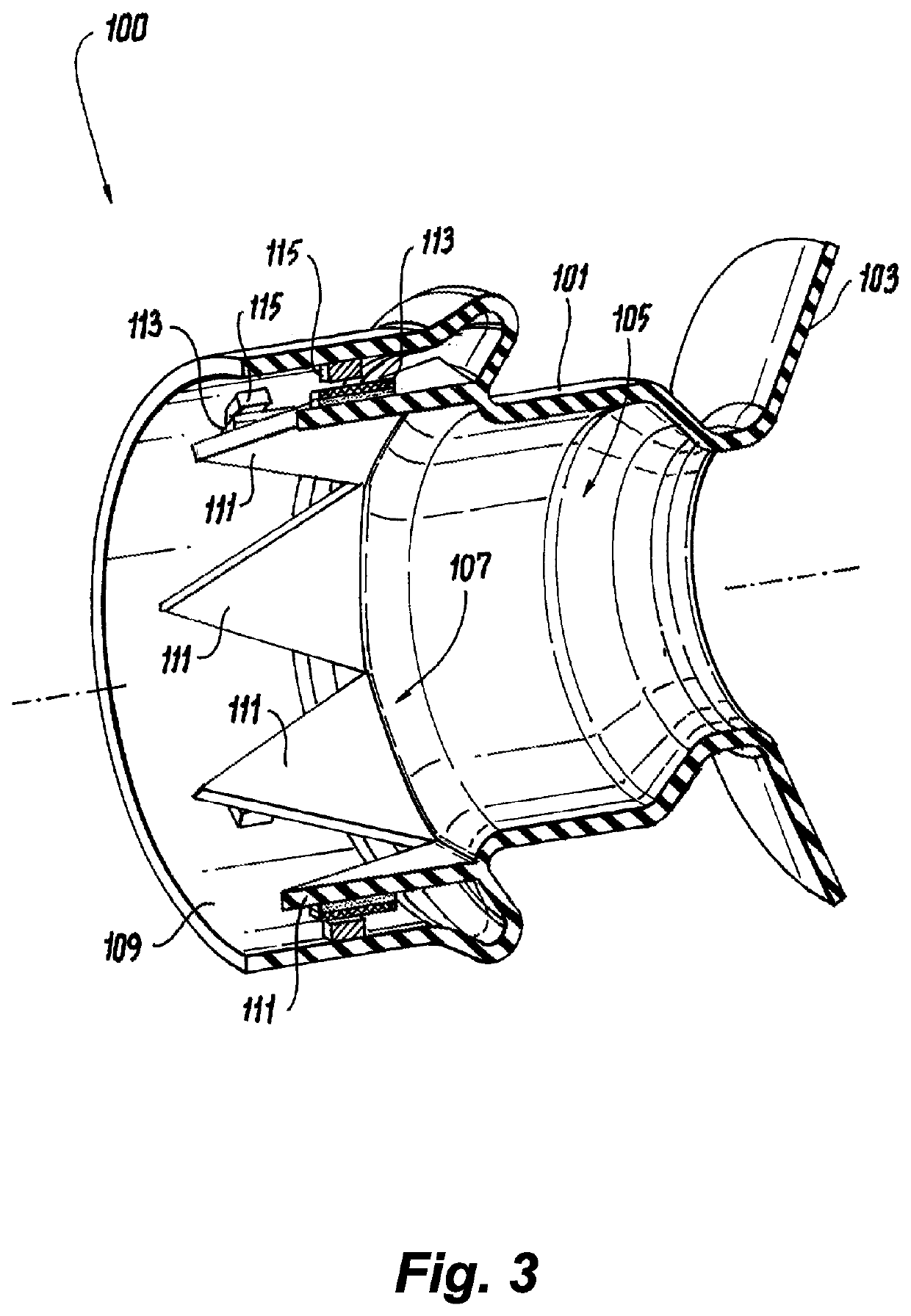
[0018]Reference will now be made to the drawings wherein like reference numerals identify similar structural features or aspects of the subject disclosure. For purposes of explanation and illustration, and not limitation, an illustrative view of an embodiment of an eyecup in accordance with the disclosure is shown in FIG. 1 and is designated generally by reference character 100. Other embodiments and / or aspects of this disclosure are shown in FIGS. 2-5.
[0019]Referring to FIGS. 1-4, an eyecup 100 for an optic (e.g., a rifle scope having a display that emits light) can include an elastic body 101 (e.g., made of rubber, silicone, or any other suitable material) forming an eye receiver 103 and a viewing cavity 105. The elastic body 101 can be configured to move between a relaxed state (e.g., as shown in FIGS. 1 and 2) and a compressed state (e.g., as shown in FIGS. 3 and 4). For example, when the eyecup 100 is mounted to an optic (e.g., on a firearm), a user can press the user's face ag...
PUM
 Abstract
Description
Claims
Application Information
 - R&D
- Intellectual Property
- Life Sciences
- Materials
- Tech Scout
- Unparalleled Data Quality
- Higher Quality Content
- 60% Fewer Hallucinations
Browse by: Latest US Patents, China's latest patents, Technical Efficacy Thesaurus, Application Domain, Technology Topic, Popular Technical Reports.
© 2025 PatSnap. All rights reserved.Legal|Privacy policy|Modern Slavery Act Transparency Statement|Sitemap|About US| Contact US: help@patsnap.com


