
Dynamic hopping plan optimization in a beam hopping satellite network

a satellite network and dynamic hopping technology, applied in the field of satellite communication systems, can solve the problems of huge interference, unconsidered practical systems, and sudden drop of transmission paths of gateways, and achieve the effect of less complex optimization algorithms and fast calculation of hopping plans

Active Publication Date: 2021-01-19
ST ENG IDIRECT EURO CY NV
View PDF9 Cites 10 Cited by
  • Summary
  • Abstract
  • Description
  • Claims
  • Application Information

AI Technical Summary

Benefits of technology

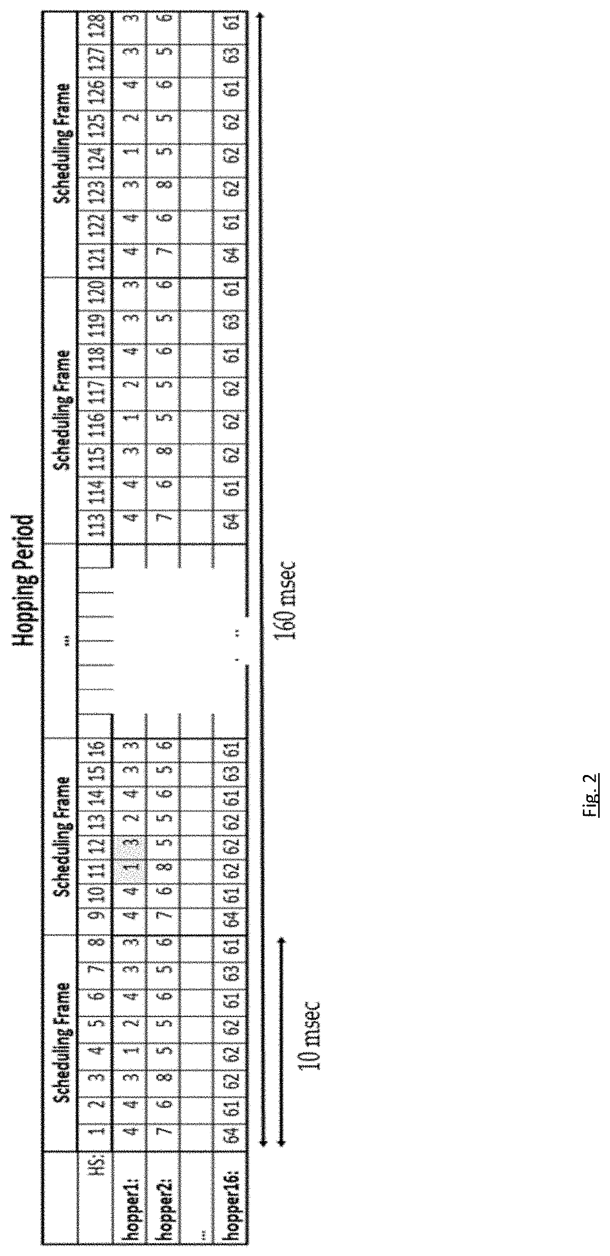
[0022]The proposed solution indeed allows for a fast calculation of an hopping plan. Due to the dynamic hopping plan calculation module it is possible to propose hopping plans which can regulate the time a contour is unserved. Further a scheduling frame is substantially shorter than a hopping period and so allows for substantially less complex optimization algorithms.

Problems solved by technology

In addition, a gateway can suddenly drop its transmission due to some failure (e.g. an electronic failure or a severe rain cloud blocking the transmission from one gateway transmitter to the satellite).
In case of flexible payloads, BH is time sharing the available power and bandwidth over multiple contours and is only limited by per hopper constraints and interference.
If, however, the terminals that can lock on non-continuous (i.e. bursty) signals are available, the transmitter does not transmit energy suppressed dummy frames and simply stops transmission.
A challenge in communicating over a beam hopping satellite is for any transmitter at any gateway to know at which time instant it must transmit a frame such that it is amplified by the satellite in the correct hopping slot.
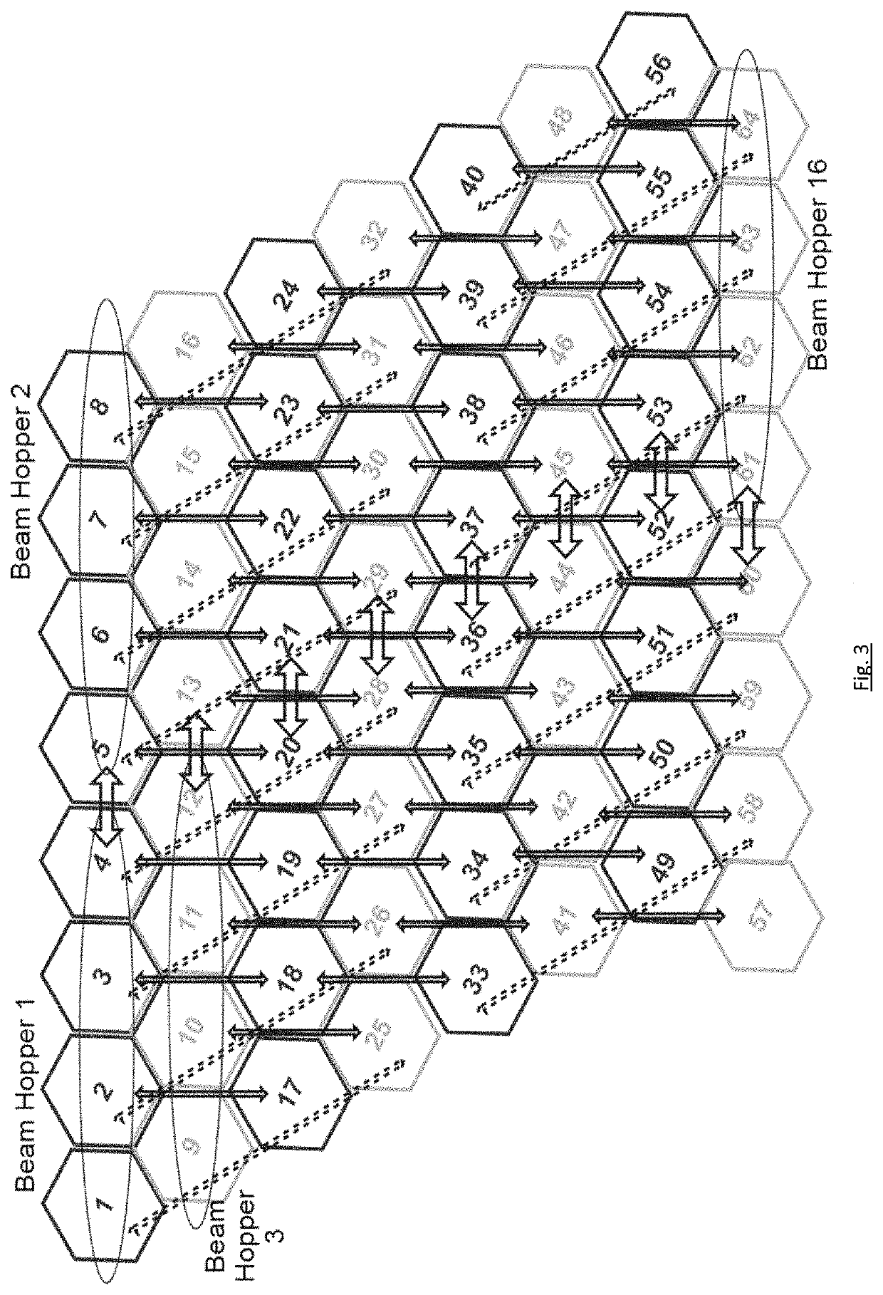
With respect to C / I, it can happen that two adjacent contours, illuminated by other beam hoppers, get illuminated at the same time at the same frequency and polarization, which would cause huge interference for terminals which are at the intersection of both beams by changing the DHP of a beam hopper.
However, such advanced signal processing techniques require exact knowledge of the multibeam channel (more specifically, all complex baseband equivalent channel gains), the terminal positions and symbol level synchronization of different carrier transmissions to terminals belonging to different satnets.
For these reasons, they are not considered practical systems so far.

Method used


Image

  • Dynamic hopping plan optimization in a beam hopping satellite network
  • Dynamic hopping plan optimization in a beam hopping satellite network
  • Dynamic hopping plan optimization in a beam hopping satellite network

Examples


Embodiment Construction

[0055]The present invention will be described with respect to particular embodiments and with reference to certain drawings but the invention is not limited thereto but only by the claims.

[0056]Furthermore, the terms first, second and the like in the description and in the claims, are used for distinguishing between similar elements and not necessarily for describing a sequence, either temporally, spatially, in ranking or in any other manner. It is to be understood that the terms so used are interchangeable under appropriate circumstances and that the embodiments of the invention described herein are capable of operation in other sequences than described or illustrated herein.

[0057]It is to be noticed that the term “comprising”, used in the claims, should not be interpreted as being restricted to the means listed thereafter; it does not exclude other elements or steps. It is thus to be interpreted as specifying the presence of the stated features, integers, steps or components as re...


PUM


Abstract

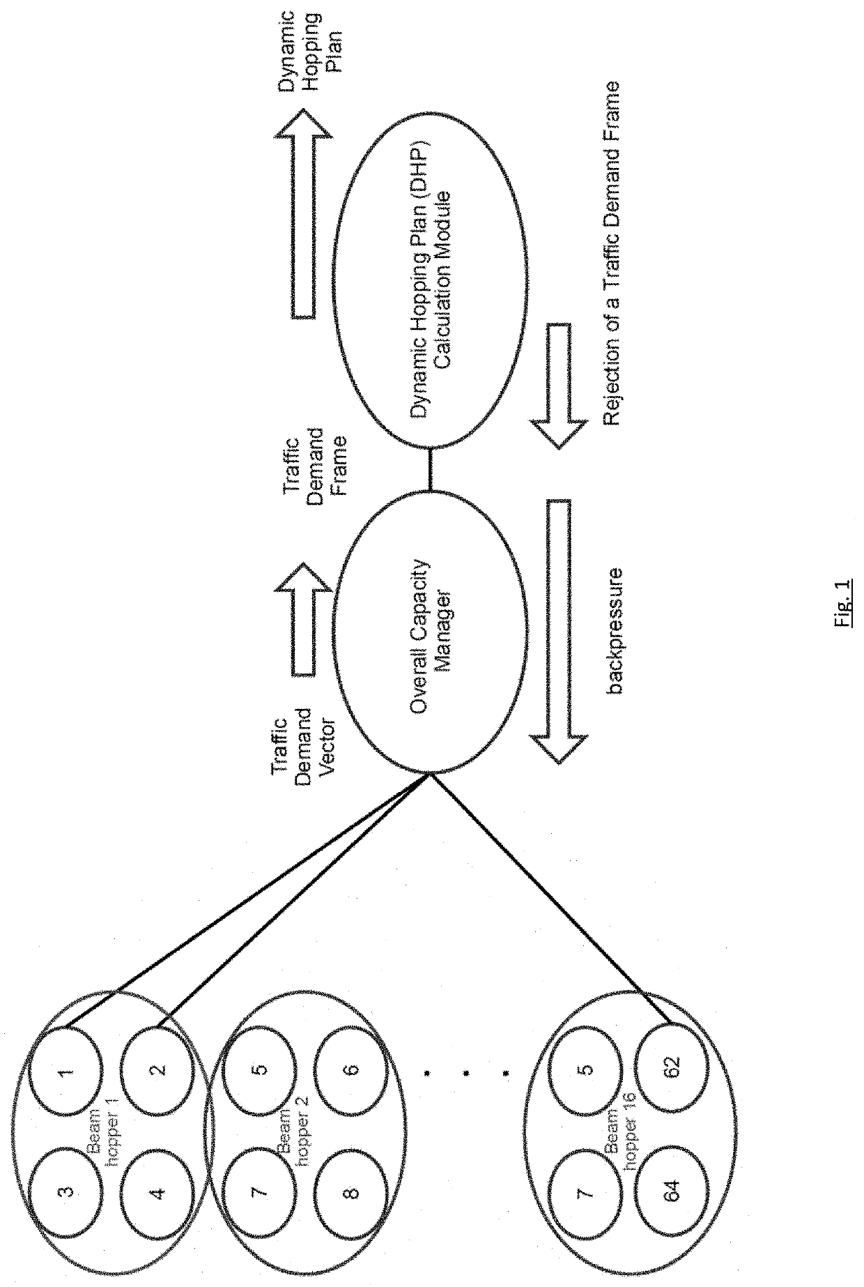
A controller device for a satellite communication system has one or more beam hoppers during a hopping period which each illuminate a plurality of contours according to a hopping plan indicating an order in which the plurality of contours is illuminated. The controller device comprises a dynamic hopping plan calculation module for calculating the hopping plan and is arranged for conveying the calculated hopping plan to a transmitter of the satellite communication system. The dynamic hopping plan calculation module is arranged to calculate the hopping plan by subdividing, per beam hopper, the hopping period in at least two scheduling frames, the at least two scheduling frames forming the calculated hopping plan. Each scheduling frame comprises hopping slots each indicating a contour to be illuminated.

Description

FIELD OF THE INVENTION[0001]The present invention is generally related to the field of satellite communication systems.BACKGROUND OF THE INVENTION[0002]The invention specifically focuses on broadband satellite networks in which one or multiple central locations, namely the hubs are connected to terrestrial internet service providers. Next, the hub connects via satellite to remote terminals providing them with access to the internet. The forward link uplink is the link between the hub and the satellite and the forward link downlink is the link between the satellite and the user terminals. In the reverse direction, the return link uplink is the link between the terminals and the satellite and the forward link downlink connects the satellite down to the hub. A typical realization is based on a star network in which a transmitter at the gateway transmits in the so-called forward (FWD) link over the satellite to multiple terminals. In case of interactive communication, the terminals tran...

Claims


Application Information

Patent Timeline
Patent Type & Authority Patents(United States)
IPC IPC(8): H04B7/08H04B7/185
CPCH04B7/088H04B7/18513H04B7/18517H04B7/18582H04B7/18586H04B7/18591H04L5/0048H04W72/046H04B7/0695
Inventor BREYNAERT, DIRKCHRISTOPOULOS, DIMITRIOS
Owner ST ENG IDIRECT EURO CY NV
Learn More