
Counter assembly

a counter and assembly technology, applied in the field of coiling machinery, can solve the problems of preventing accurate measurement, spools can be extremely heavy, coil machines lie with the counters used, etc., and achieve the effect of increasing the versatility of the counter assembly and minimizing the inaccuracy of measuremen

Active Publication Date: 2021-01-19
NEWGENT JAMES +1
View PDF5 Cites 0 Cited by
  • Summary
  • Abstract
  • Description
  • Claims
  • Application Information

AI Technical Summary

Benefits of technology

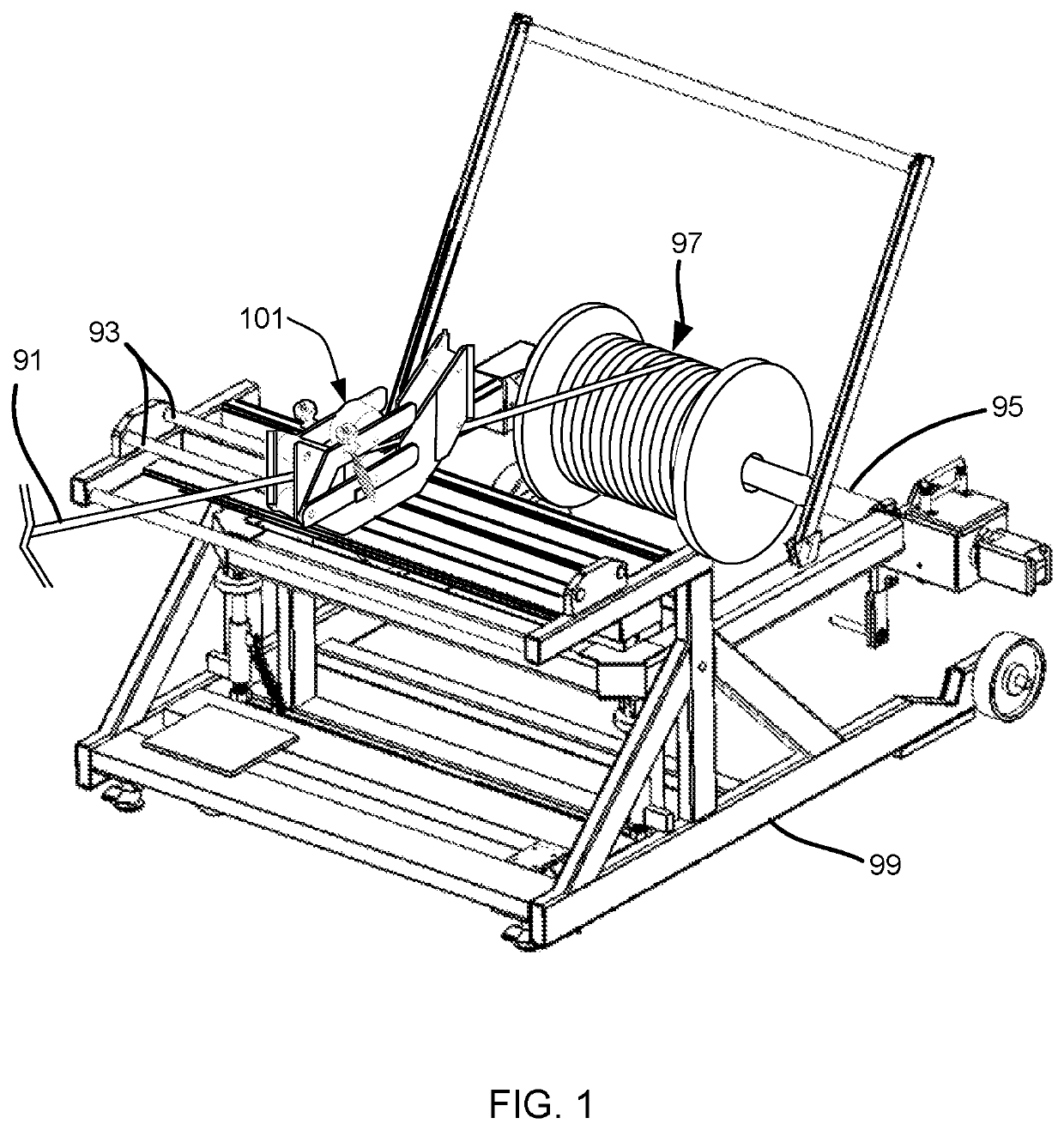
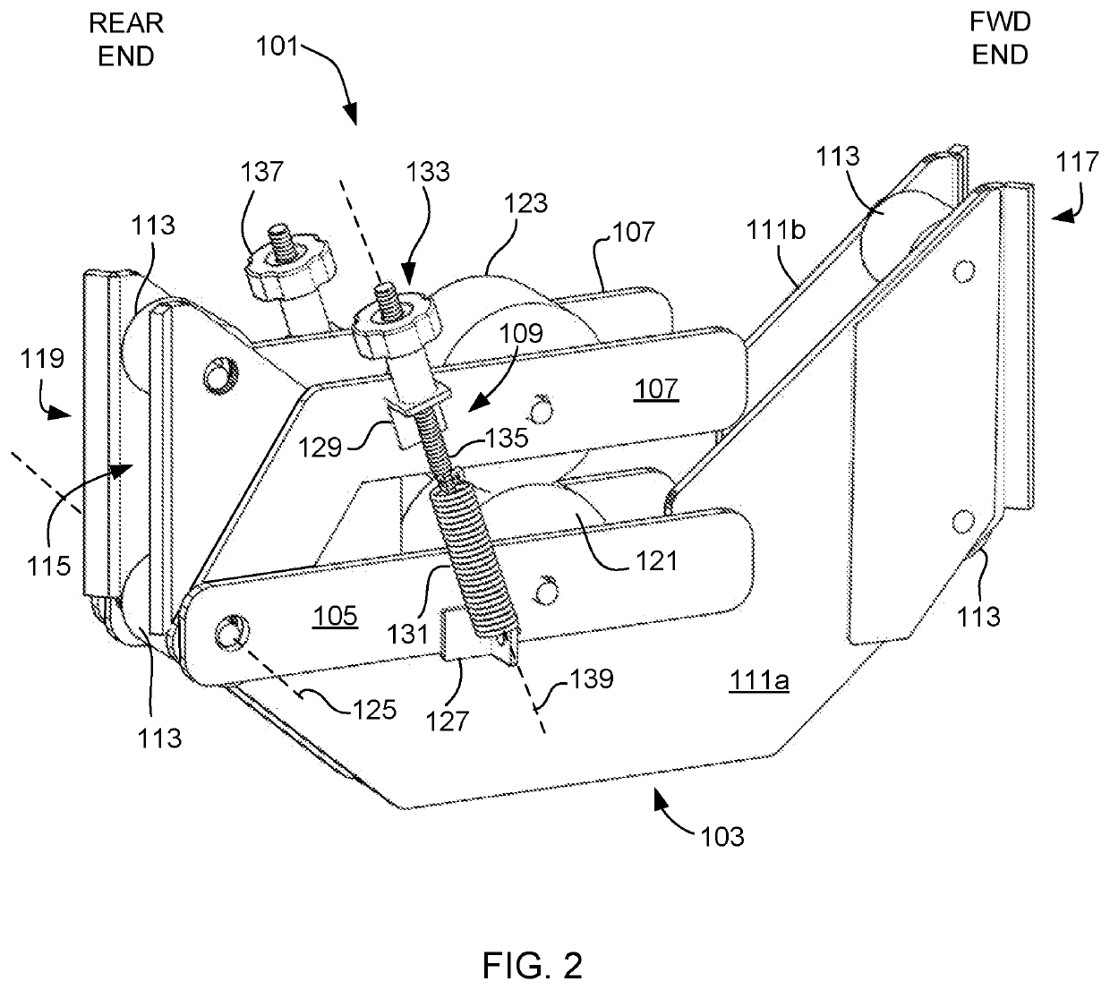
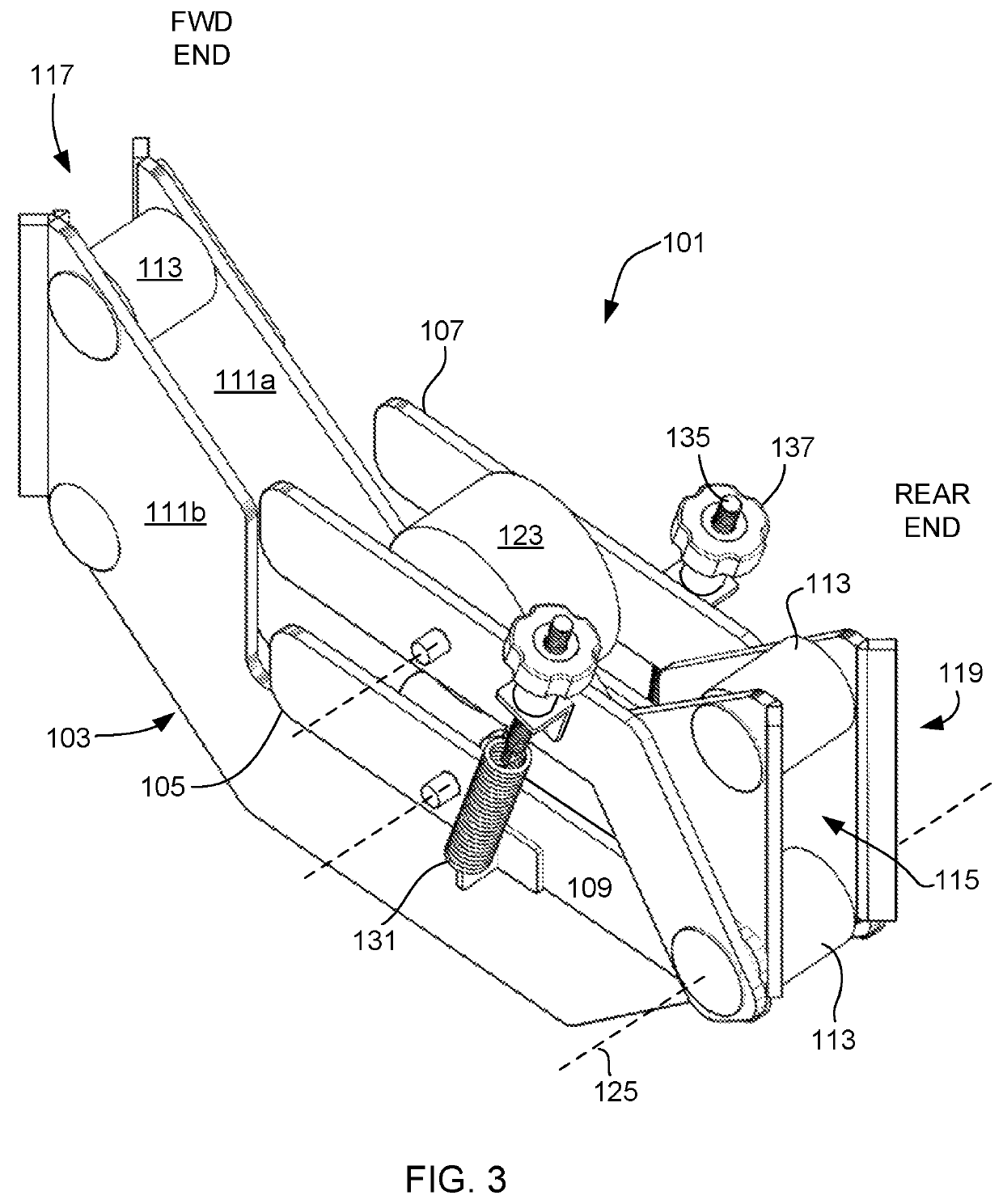
The present patent application describes a counter assembly for measuring line on a reel. The assembly includes a body with adjustable rollers that allow the line to pass through. The rotation of the rollers is converted to a linear distance for accurate measurement. The assembly is designed to minimize inaccuracies and is flexible with different sizes and materials of line. It also includes a springs and tensioner assembly that is oriented to minimize bouncing of the arms and the resting spring force between the arms can be adjusted.

Problems solved by technology

Depending on the size of the cable and spool, these spools can be extremely heavy.
A disadvantage of these coil machines lie with the counters used.
The problem arises with the orientation of springs used to combat undesired separation of the rollers.
The bouncing prevents accurate measurement.
These springs produce a constant and unadjustable tension spring force pulling the arms back together.
Although springs are useful to an extent, their use is also prohibitive.
The spring force of one set of springs is not sufficient for the use on all types of line / cable / wire.
As each line has a different diameter, and is made from a different material(s) of varied harness, the spring forces from a set of springs can hinder the versatility of the counter assembly.

Method used


Image

  • Counter assembly
  • Counter assembly
  • Counter assembly

Examples


Embodiment Construction

[0023]Illustrative embodiments of the preferred embodiment are described below. In the interest of clarity, not all features of an actual implementation are described in this specification. It will of course be appreciated that in the development of any such actual embodiment, numerous implementation-specific decisions must be made to achieve the developer's specific goals, such as compliance with assembly-related and business-related constraints, which will vary from one implementation to another. Moreover, it will be appreciated that such a development effort might be complex and time-consuming but would nevertheless be a routine undertaking for those of ordinary skill in the art having the benefit of this disclosure.

[0024]In the specification, reference may be made to the spatial relationships between various components and to the spatial orientation of various aspects of components as the devices are depicted in the attached drawings. However, as will be recognized by those skil...


PUM


Abstract

A counter assembly for use with coiling machinery for the measurement of line being wound or unwound on a reel includes a body, an upper arm, a lower arm, and a tensioner assembly. The body defines a central channel for passage of the line. Rollers are coupled to the upper and lower arms and used to press against the line. Movement of the line between the rollers causes at least one roller to rotate. Rotation is converted to a linear distance for accurate measurement. The upper arm has a pivot axis that is below a horizontal portion of the upper arm and is shared with the lower arm. The tensioner assembly is oriented to share the same vector components of motion as the pivoting upper arm. The tensioner assembly also permits adjustment in the resting spring force acting on the rollers.

Description

BACKGROUND1. Field of the Invention[0001]The present application relates to coiling machinery for the winding and unwinding of coil reels, and more particularly to a counter assembly for measuring the amount of line that is unwound or wound on the reel.2. Description of Related Art[0002]Metallic cables and wires are used in many types of applications within industry. These cables are stored typically on a reel or spool because these cables and wires are very long and the act of wrapping them around a cylindrical spool is a fairly efficient way to store, transport, and use them without concern for bending or creasing the cables. Coiling machinery is used to assist in the winding and unwinding of these spools of cable. Depending on the size of the cable and spool, these spools can be extremely heavy. The coiling machinery therefore has to be built to be very sturdy and stable. This machinery typically includes a means of elevating the spool off the floor and a means of counting the am...

Claims


Application Information

Patent Timeline
Patent Type & Authority Patents(United States)
IPC IPC(8): B65H59/06B65H61/00
CPCB65H59/06B65H61/00B65H2701/36
Inventor NEWGENT, JAMESNEWGENT, TAMMY
Owner NEWGENT JAMES
Learn More