Fail-safe speed monitoring of a drive

a technology of fail-safe speed monitoring and drive, which is applied in the direction of instruments, web handling, transportation and packaging, etc., can solve the problem that the closed-loop control does not allow the detection of all sensor errors

Active Publication Date: 2021-01-05
SIEMENS ENERGY GLOBAL GMBH & CO KG
View PDF14 Cites 0 Cited by
  • Summary
  • Abstract
  • Description
  • Claims
  • Application Information

AI Technical Summary

Benefits of technology

[0007]In accordance with the invention, fail-safe speed monitoring is realized via a calculation method in the software using the existing / conventional hardware, i.e., there is no requirement for special hardware such as that required in conventional solutions (safety sensors, etc.). Here, the substitute rotational speed is calculated from the output frequency of the converter in the case of three-phase drives, and from the quotient of EMF (electromotive force or terminal voltage) and magnetic flux in the case of direct-current drives. By virtue of the three plausibility checks (target rotational speed—actual rotational speed, actual rotational speed—substitute rotational speed, substitute rotational speed—target rotational speed) it is possible to achieve safety levels that could previously only be achieved via hardware solutions.
[0011]In a further advantageous embodiment, the actual rotational speed and / or the substitute rotational speed are checked in the safety program to determine whether they exceed at least one specified positive limit value, or whether they do not reach at least one specified negative limit value. The calculated substitute rotational speed is independent of the sensor. Consequently, verifying whether the substitute rotational speed exceeds a limit value ensures the safety of the system even in the case of certain sensor errors (e.g., constant slip between sensor and sensor shaft).
[0012]In a further advantageous embodiment, a warning signal is output and / or the motor is switched off if the positive limit value is exceeded or the negative limit value is not reached. The output of a warning signal allows an operator to adopt suitable measures and if applicable to additionally switch the motor off manually. However, the limit value can also be specified such that the motor is switched off immediately.

Problems solved by technology

For a method without the calculated substitute rotational speed, the feedback of target value and actual value (actual value captured by sensor) via closed-loop control does not allow the detection of all sensor errors that must be detected in order to achieve fail-safe speed monitoring, such as constant slip between sensor and sensor shaft.

Method used


Image

  • Fail-safe speed monitoring of a drive
  • Fail-safe speed monitoring of a drive

Examples


Embodiment Construction

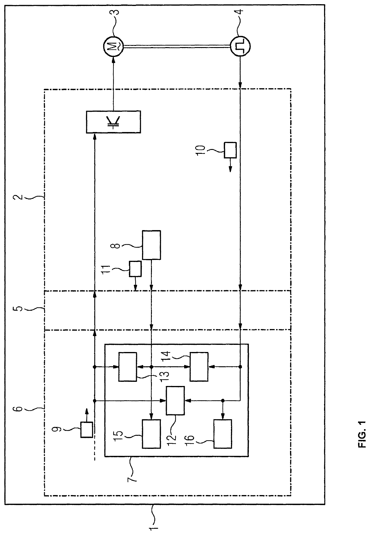
[0021]FIG. 1 shows a system 1 comprising a drive, which has a converter 2, a motor 3 and a rotational speed sensor 4, and a safety CPU 6 with a safety program 7. Converter 2 and safety CPU 6 are coupled together, e.g., via a field bus 5 as a communication connection. In the exemplary embodiment illustrated, the converter 2 itself has means 8 for calculating a substitute rotational speed 11. The substitute rotational speed 11 here is calculated from the output frequency of the converter 2 in the case of three-phase drives or the quotient of EMF (electromotive force or terminal voltage) and magnetic flux in the case of direct-current drives. A target rotational speed 9 is specified to the converter 2, and the rotational speed sensor 4 returns an actual rotational speed 10.

[0022]Two of these three rotational speed values are now each verified in the safety program 7 of the safety CPU 6 for plausibility, i.e., a plausibility verification 12 occurs between the target rotational speed 9 a...


PUM


Abstract

A method for fail-safe monitoring of the speed of a drive that includes at least a converter, a motor, and a rotational speed sensor, wherein a target rotational speed is specified to the drive and an actual rotational speed is sensed via the sensor, where a substitute rotational speed is calculated and three plausibility checks are performed in a safety program of a safety CPU, the substitute rotational speed being determinable, for example, from the initial frequency of a converter or from the quotient of EMF and magnetic flux, in each case two of the following three values being checked: target rotational speed, actual rotational speed and substitute rotational speed to achieve a high safety integrity level while avoiding disadvantages of conventional solutions, and because the calculated substitute rotational speed is independent of the sensor, even sensor errors that are difficult or impossible to detect via conventional solutions become detectable.

Description

CROSS-REFERENCE TO RELATED APPLICATIONS[0001]This is a U.S. national stage of application No. PCT / EP2016 / 077273 filed Nov. 10, 2016. Priority is claimed on EP Application No. 15200824 filed Dec. 17, 2015, the content of which is incorporated herein by reference in its entirety.BACKGROUND OF THE INVENTION1. Field of the Invention[0002]The invention relates to a method for fail-safe monitoring of the speed of a drive, which has at least a converter, a motor and a rotational speed sensor, wherein a target rotational speed is specified to the drive and an actual rotational speed is captured by means of the rotational speed sensor, and also relates to a system comprising at least one drive, which has at least the converter, the motor and the rotational speed sensor, and means for performing the cited method, where the cited method is used to indirectly monitor the web speed of a material web which is moved by rollers in a paper machine, reel slitter or coater.2. Description of the Relate...

Claims


Application Information

Patent Timeline
Patent Type & Authority Patents(United States)
IPC IPC(8): B65H26/00G01D5/244B65H18/18H02H7/08H02H7/093
CPCG01D5/24461B65H18/18G01D5/24466H02H7/0844H02H7/093B65H26/00G01P3/48G01P21/02H02P29/10B65H23/192B65H2513/11B65H2801/84B65H2513/10B65H2220/01B65H2220/02
Inventor CZERNY, WERNERMEINARDUS, MARTINRASENACK, WOLF-MARTINVLAIC, IULIU
Owner SIEMENS ENERGY GLOBAL GMBH & CO KG
Why Eureka
Try Eureka