
Foam backed panel with cantilever

a technology of foam and support panel, which is applied in the direction of walls, chemistry apparatus and processes, synthetic resin layered products, etc., can solve the problems of no prior art combining the continuous condition with the fixed boundary condition of low modulus of elasticity materials such as foam or foam composite panels, and achieves the effects of reducing the flexural stiffness

Active Publication Date: 2020-12-15
KREIZINGER KENNETH R
View PDF14 Cites 1 Cited by
  • Summary
  • Abstract
  • Description
  • Claims
  • Application Information

AI Technical Summary

Benefits of technology

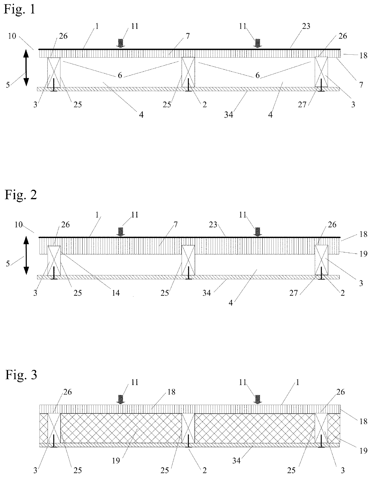
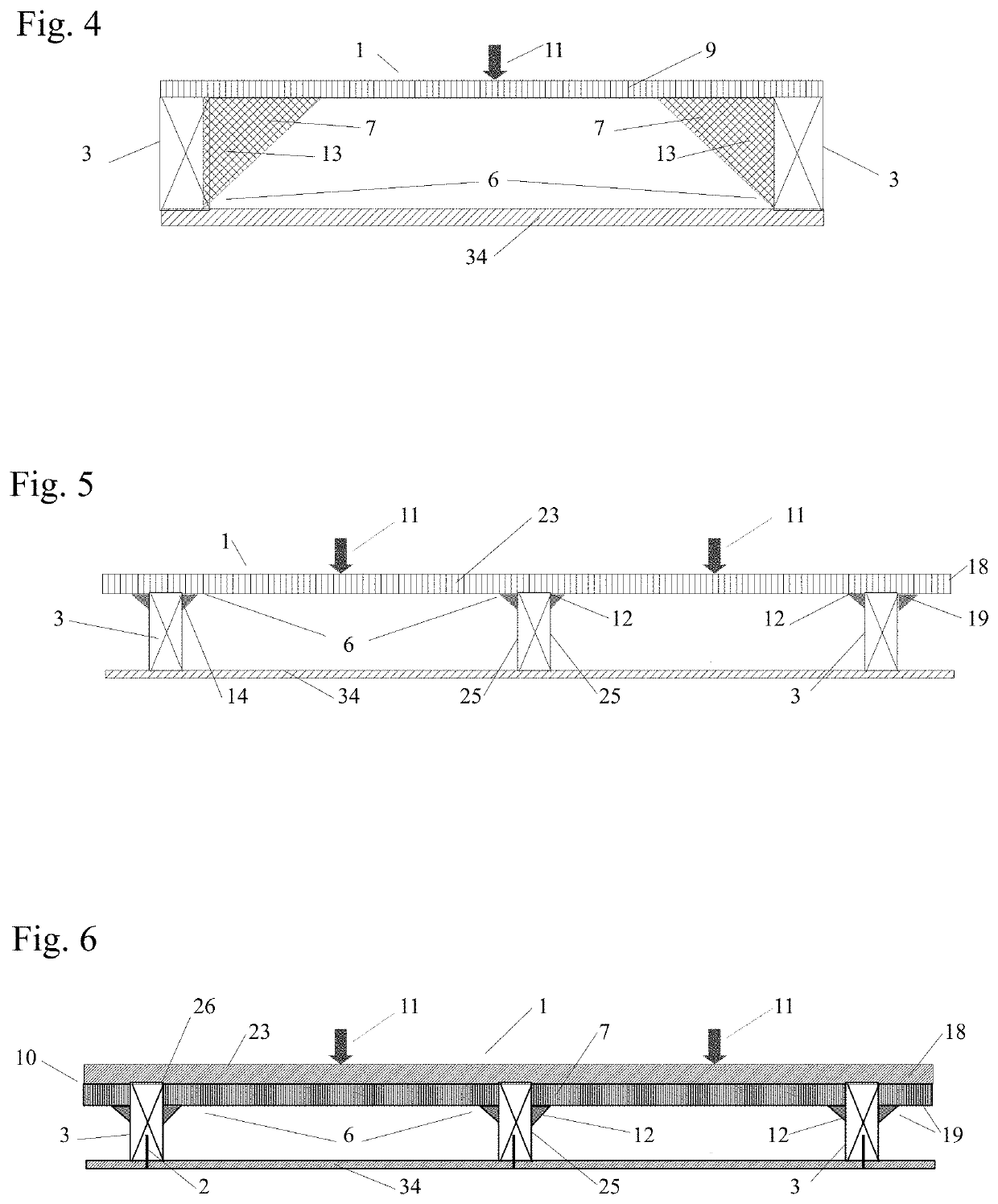
[0021]The inventive subject matter is the application of four new conditions on weaker, lighter, thinner and less costly panels to enable them to become stiffer, stronger and more versatile by re-configuring the panel's shape and / or by sufficiently bonding the panel to frame members. The effectiveness of these new conditions is inversely related to a panel's flexural stiffness in that the smaller the flexural stiffness the greater the effect the conditions have in increasing a panel's load capacity. Panels with the lowest flexural stiffness can have thousands of times increases in load capacities. As a result, non-structural materials, such as foam insulation, may be converted into structural applications to facilitate a new generation of multi-functional structural panels.

Problems solved by technology

However, no prior art combines the continuous condition with the fixed boundary condition on low modulus of elasticity materials such as foam or foam composite panels.
In addition, despite substantial prior art showing a polyurethane foam composite panel in a continuous condition and bonded to frame members, either the configuration didn't induce a fixed boundary condition or if it did, it was unrecognized.
Finally, the techniques used on steel, reinforced concrete and wood to attain a fixed boundary condition are not transferable to foam.

Method used


Image

  • Foam backed panel with cantilever
  • Foam backed panel with cantilever
  • Foam backed panel with cantilever

Examples


Embodiment Construction

[0109]The inventive subject matter is the application of four new conditions on weaker, lighter, thinner and less costly panels to enable them to become stiffer, stronger and more versatile by re-configuring the panel's shape and / or by sufficiently bonding the panel to frame members. The newly discovered conditions are: a fixed / continuous condition, a continuous / dropped condition, a fixed / continuous / dropped condition and an enhanced continuous condition. The effectiveness of these new conditions is inversely related to a panel's flexural stiffness in that the smaller the flexural stiffness the greater the effect the conditions have on increasing a panel's load capacity. As a result, low flexural stiffness and typically non-structural materials, such as foam insulation, may be converted into structural panels to facilitate a new generation of multi-functional structural panels.

[0110]Several tests were undertaken on panels made of a low modulus of elasticity materials or panels with a...


PUM

PropertyMeasurementUnit
span lengthaaaaaaaaaa

Abstract

A frame supported, foam composite panel with a cladding backed by polyurethane foam bonding the cladding to the frame. The panel has a cantilevered extension projecting beyond the frame to enable the panel to overlap the outside edge of a column, beam, floor or other structure the panel is attached to. The cantilevered section may have reinforcing ribs embedded in the foam and may have a sealing material between the cantilever and the structure it overlays.

Description

CROSS REFERENCE TO RELATED APPLICATIONS[0001]This application is a continuation-in-part of application Ser. No. 15 / 921,379 filed Mar. 14, 2018 and which claims the benefit of the filing date of continuation-in-part application Ser. No. 15 / 337,138, filed Oct. 28, 2016 and which claims the benefit of the filing date of continuation-in-part application Ser. No. 14 / 738,851, filed Jun. 13, 2015, and which claims the benefit of the filing date of U.S. Provisional Application Nos. 62 / 018,551 filed Jun. 28, 2014 and 62 / 033,420 filed Aug. 5, 2014, all of which above cited applications are hereby incorporated by reference.INVENTION BACKGROUND[0002]The inventive subject matter comprises is a frame supported panel utilizing four new conditions that enable weaker, lighter and thinner panels to be made stiffer and more versatile by re-configuring the panel's shape and / or by sufficiently bonding the panel to frame members. These conditions substantially increase the stiffness and load strength of ...

Claims


Application Information

Patent Timeline
Patent Type & Authority Patents(United States)
IPC IPC(8): E04B9/00B32B27/40E04C2/38B32B7/12E04B2/00E04B1/14E04B2/72E04C2/34E04B2/70
CPCB32B7/12E04B2/721E04C2/38B32B27/40E04C2/46E04B2/707E04B1/14E04C2/34E04B2103/04E04C2002/3488E04C2/205E04C2/296
Inventor KREIZINGER, KENNETH R.
Owner KREIZINGER KENNETH R
Learn More