
Soil washing process and apparatus

a technology of soil washing and washing machine, which is applied in the direction of cleaning process and equipment, solid separation, cleaning using liquids, etc., can solve the problems of affecting the quality of soil cleaning, and requiring a considerable amount of effort to remove or remediate soil contamination,

Active Publication Date: 2020-12-08
ESTEP ALLEN SHANE
View PDF3 Cites 2 Cited by
  • Summary
  • Abstract
  • Description
  • Claims
  • Application Information

AI Technical Summary

Benefits of technology

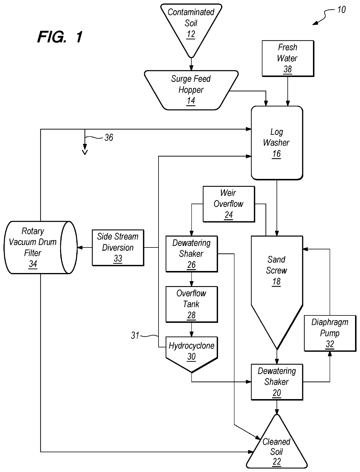
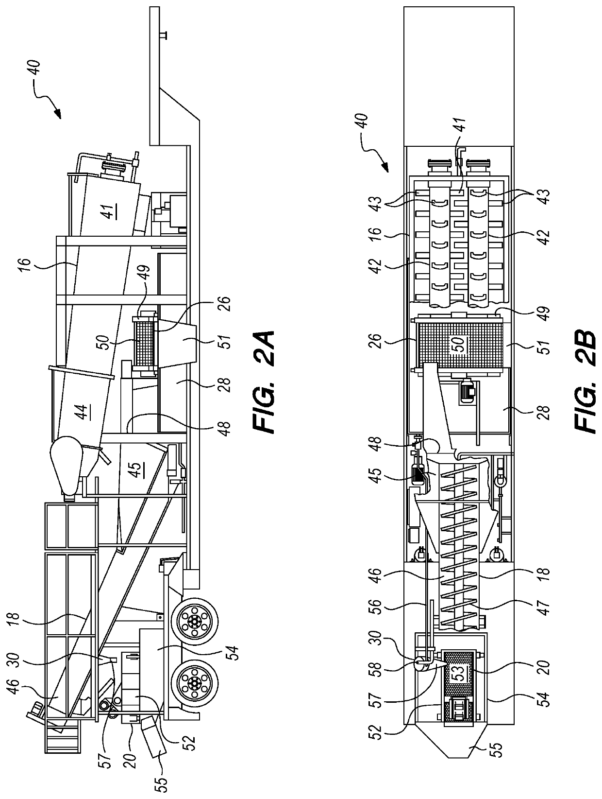
The patent text describes an apparatus and method for separating water and soil using a log washer, sand screw, dewatering shaker, and hydrocyclone separator. The apparatus receives water and contaminated soil, mixes them with paddles on log shafts, separates them with a weir box and weir, and dewaters them. The method separates the soil and water mixture into two streams, dewaters the first stream, collects the organic materials in the second stream, and separates the water stream into non-colloidal particulates and colloid-containing water. The technical effects include improved efficiency in separating water and soil, recycling of non-colloidal materials, and reduction of colloid pollution.

Problems solved by technology

Soil may become contaminated with various materials, chemicals and substances for a wide range of reasons.
Once contaminated, it may take a considerable effort to remove or remediate the contamination from the soil.
Any removal or remediation of soil can become expensive due to the cost associated with the excavation, transportation, disposal of the waste and the transportation of clean backfill back to the site to fill the excavation.
As an example, water that is produced during oil and gas production may occasionally escape containment and contaminate the nearby soil.
The produced water often contains high concentrations of dissolved solids, including salts, which may damage the ecology of the affected area.

Method used


Image

  • Soil washing process and apparatus
  • Soil washing process and apparatus
  • Soil washing process and apparatus

Examples


Embodiment Construction

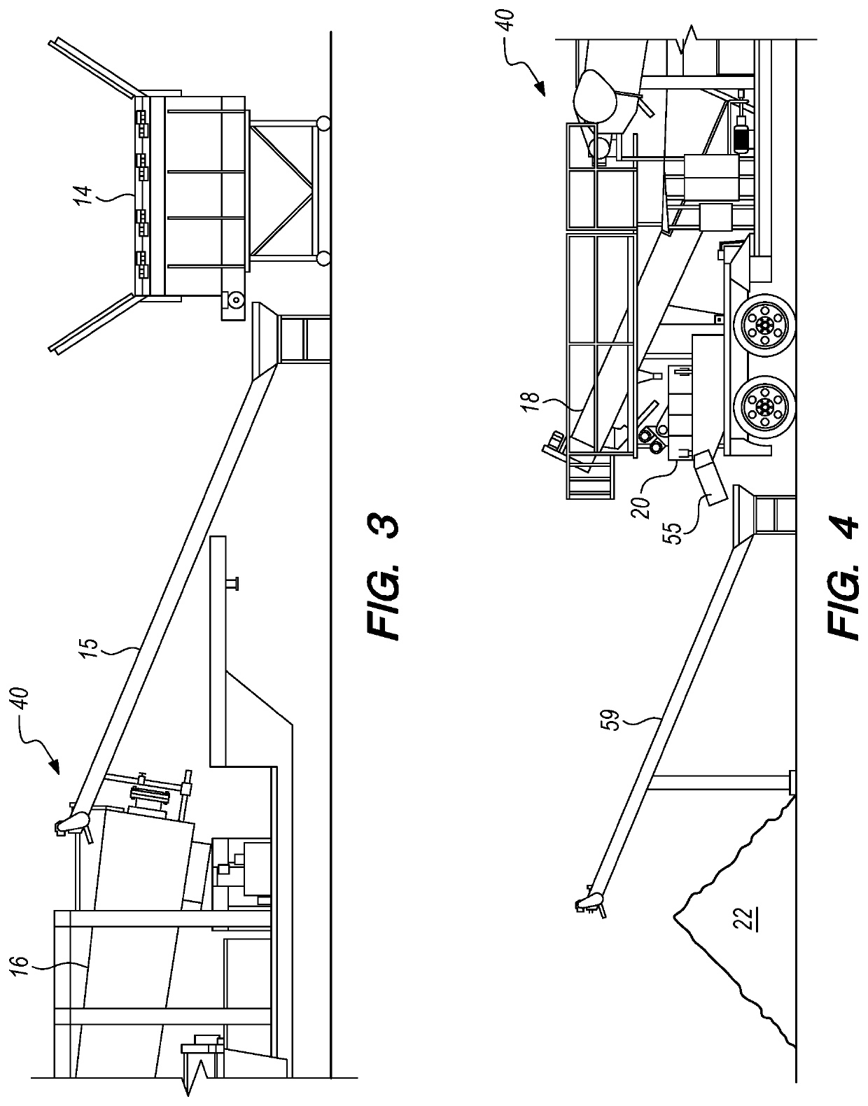
[0013]One embodiment provides an apparatus comprising a log washer, sand screw, first dewatering shaker and a hydrocyclone separator. The log washer has a feed end for receiving water and contaminated soil, two or more log shafts with paddles for mixing the soil and water, and a discharge end for discharging the soil and water mixture. The sand screw has a lower end forming a weir box, an upper discharge end, and a screw that draws wet soil collecting in the bottom of the weir box from the lower end to the upper discharge end while allowing water to drain out of the wet soil into the weir box, wherein the weir box is positioned below the discharge end of the log washer to receive the soil and water mixture discharged from the log washer, and wherein the weir box includes a weir allowing water and floating organic materials to flow over the weir. The first dewatering shaker has a shaker table for receiving the wet soil discharged from the upper discharge end of the sand screw, a scre...


PUM


Abstract

A soil washing process includes mixing water and contaminated soil in a log washer, separating the soil and water mixture into a first stream of wet soil and a second stream of water and floating organic materials, dewatering the first stream of wet soil to form a cleaned soil stream, dewatering the second stream to separate out the organic materials and form a water stream, separating the water stream into a stream of non-colloidal particulates and a stream of colloid-containing water, dewatering the stream of non-colloidal particulates, and adding the stream of colloid-containing water to the soil and water mixture. The method may further include returning a first portion of the colloid-containing water to the log washer, and drawing off a second portion of the colloid-containing water to filter out the colloids before returning a clean water stream to the log washer.

Description

BACKGROUND[0001]The present disclosure relates to methods and apparatus for cleaning contaminated soil.BACKGROUND OF THE RELATED ART[0002]Soil may become contaminated with various materials, chemicals and substances for a wide range of reasons. Once contaminated, it may take a considerable effort to remove or remediate the contamination from the soil. Any removal or remediation of soil can become expensive due to the cost associated with the excavation, transportation, disposal of the waste and the transportation of clean backfill back to the site to fill the excavation.[0003]As an example, water that is produced during oil and gas production may occasionally escape containment and contaminate the nearby soil. The produced water often contains high concentrations of dissolved solids, including salts, which may damage the ecology of the affected area. As a result, removal and / or remediation of the soil may become necessary to reduce the salt content of the soil.BRIEF SUMMARY[0004]One...

Claims


Application Information

Patent Timeline
Patent Type & Authority Patents(United States)
IPC IPC(8): B09C1/02B03B5/02B08B3/08
CPCB09C1/02B03B5/02B08B3/08
Inventor ESTEP, ALLEN SHANEHARRIS, DARREN DAVIS
Owner ESTEP ALLEN SHANE
Learn More