Expandable inter-vertebral cage and method of installing same
a technology of intervertebral cage and extension, which is applied in the field of spine diseases, can solve the problems of torsion stress on the hinge element, and achieve the effect of reducing the number of potential complications and optimal placement in the intervertebral spa
- Summary
- Abstract
- Description
- Claims
- Application Information
AI Technical Summary
Benefits of technology
Problems solved by technology
Method used
Image
Examples
first embodiment
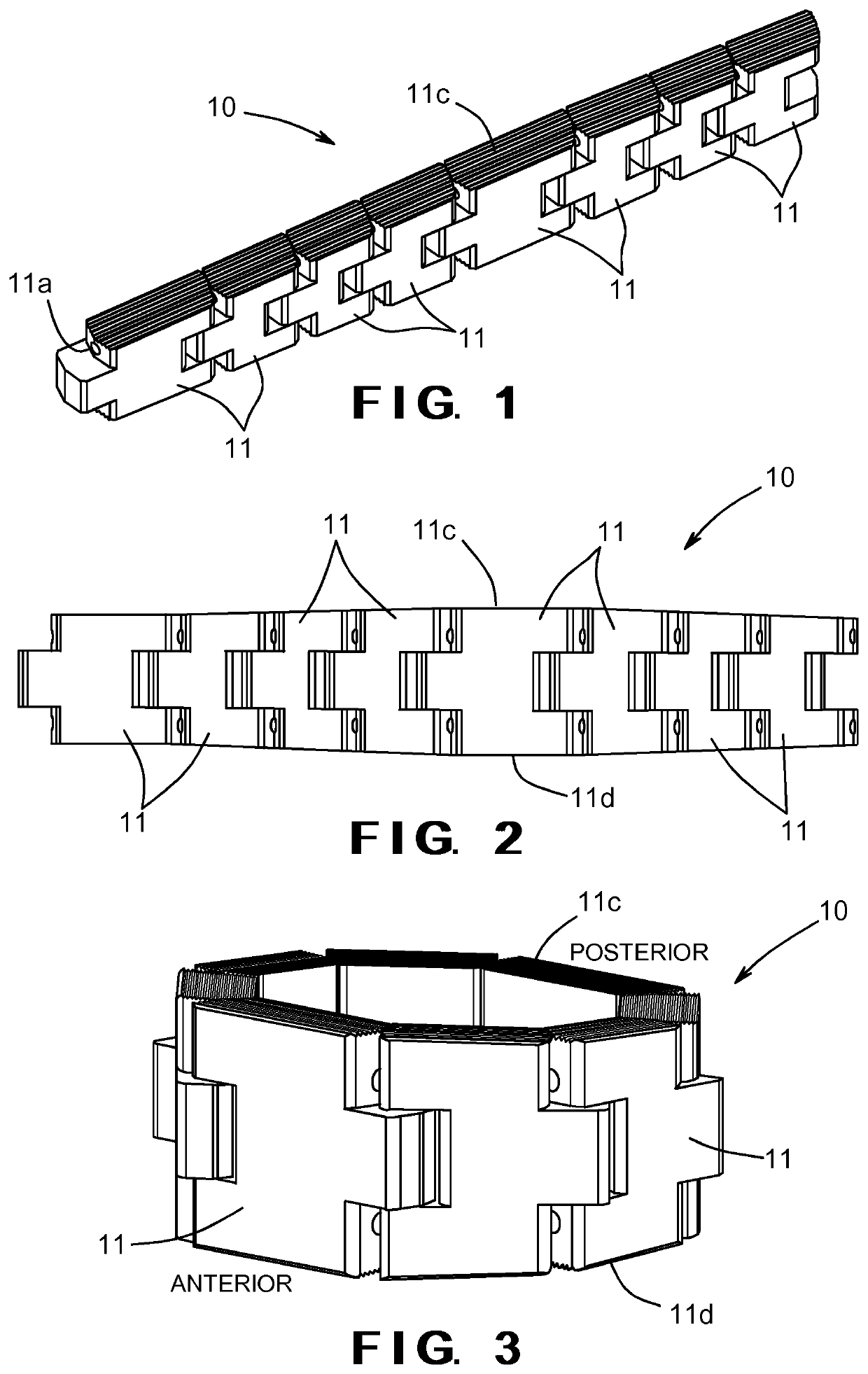
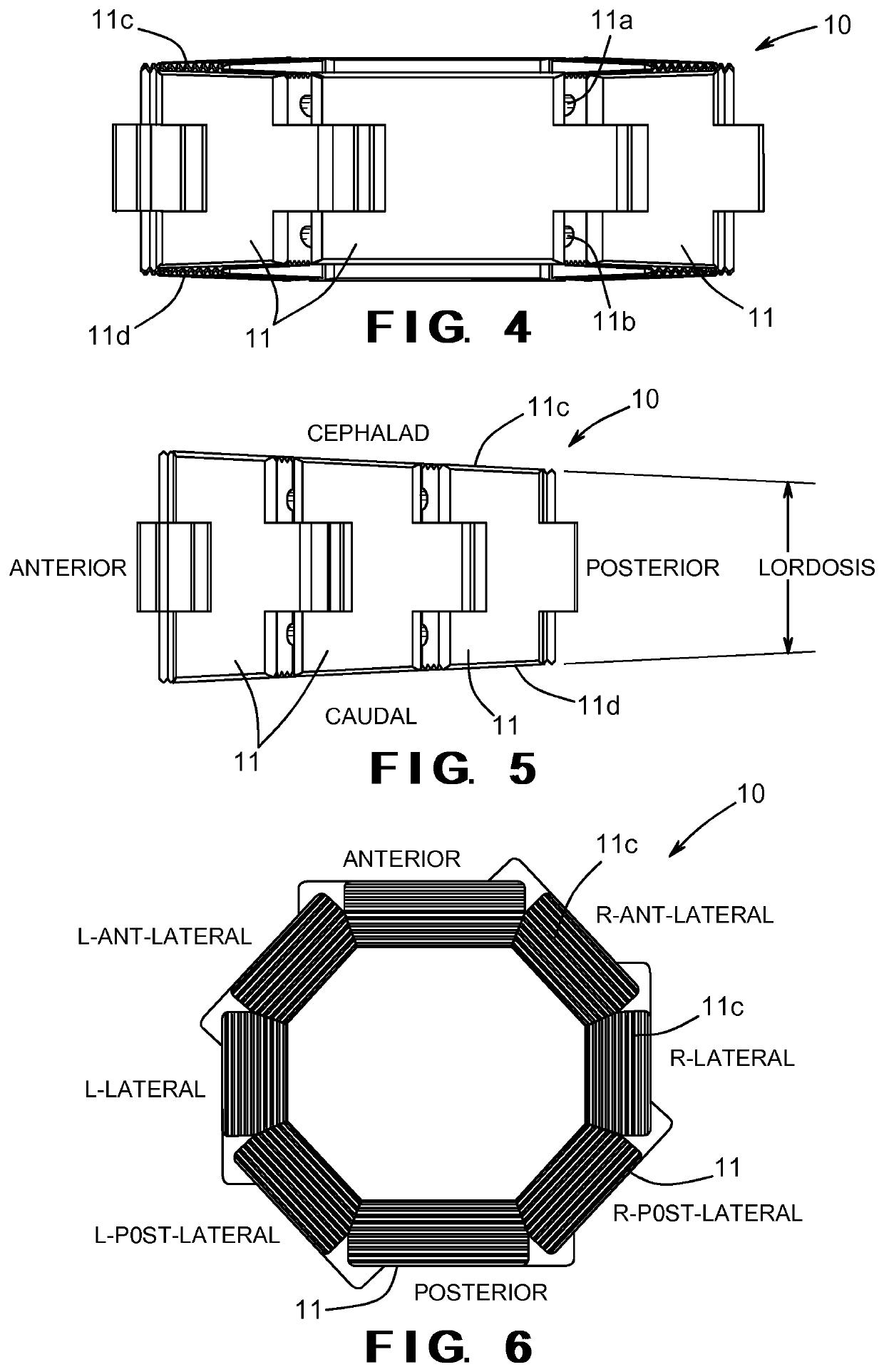
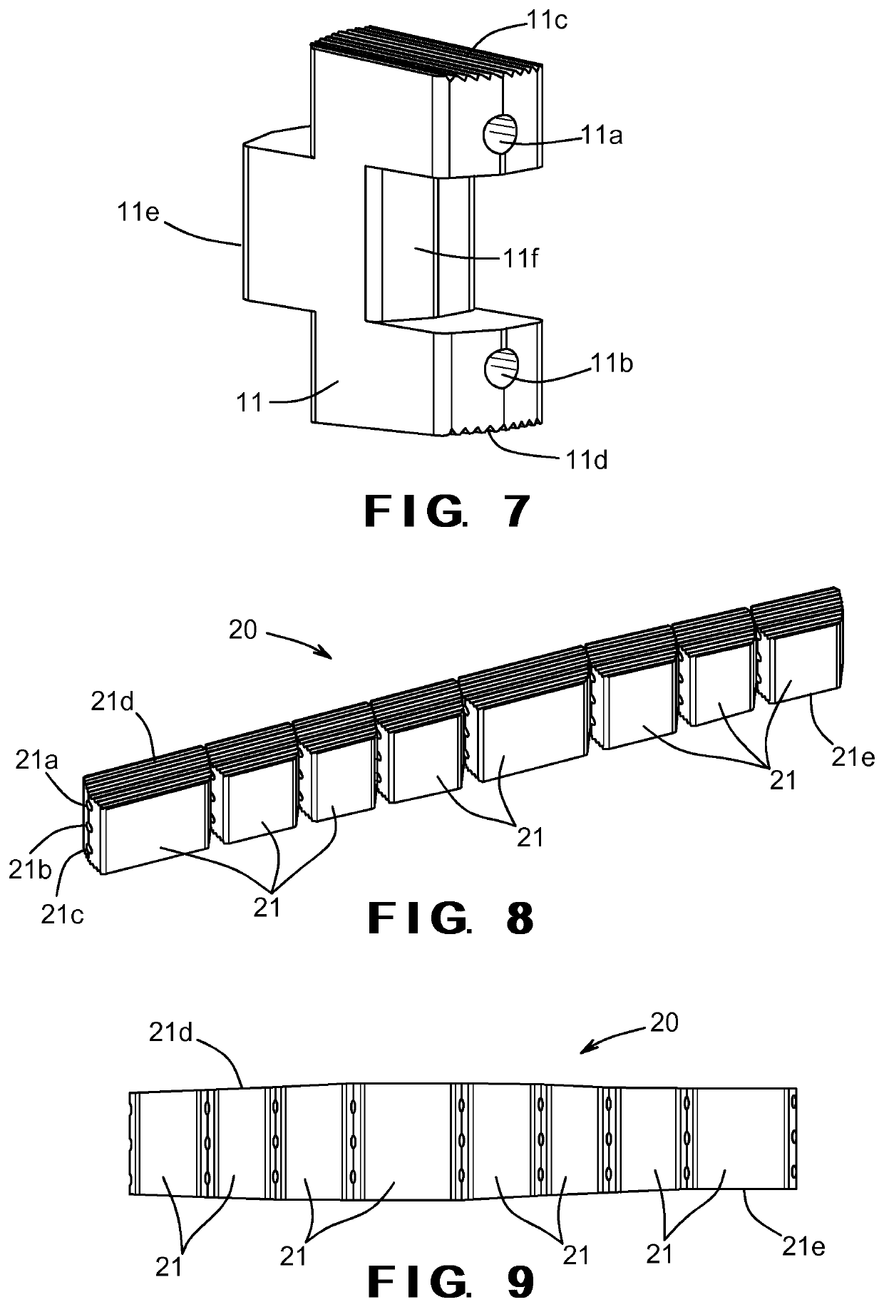
[0045]FIGS. 1 through 7 illustrate the intervertebral cage, indicated generally at 10, in accordance with this invention. FIGS. 1 and 2 show the cage 10 in an initial orientation, which is the normal orientation of the cage 10 before implantation / insertion inside an intervertebral space, as discussed above. FIGS. 3 through 6 show the cage 10 is an expanded orientation, which is the normal orientation of the cage 10 after implantation / insertion inside an intervertebral space, as discussed above.
[0046]The illustrated cage 10 includes eight individual segments 11, although a greater or lesser number of same may be provided as desired. Each of the illustrated segments 11 has a first passageway 11a and a second passageway 11b formed therethrough, although such is not required. The first passageways 11a are preferably aligned with one another so that a first wire 30 (see FIG. 15) can extend through all of the segments 11. Similarly, the second passageways 11b are also preferably aligned w...
second embodiment
[0051]FIGS. 8 through 14 illustrate the intervertebral cage, indicated generally at 20, in accordance with this invention. FIGS. 8 and 9 show the cage 20 in an initial orientation, which is the normal orientation of the cage 20 before implantation / insertion inside an intervertebral space, as discussed above. FIGS. 10 through 13 show the cage 20 is an expanded orientation, which is the normal orientation of the cage 20 after implantation / insertion inside an intervertebral space, as discussed above.
[0052]The illustrated cage 20 includes eight individual segments 21, although a greater or lesser number of same may be provided as desired. Each of the illustrated segments 21 has a first passageway 21a, a second passageway 21b, and a third passageway 21c formed therethrough, although such is not required. The first passageways 21a are preferably aligned with one another so that a first wire 30 can extend through all of the segments 21. Similarly, the second and third passageways 21b and 2...
third embodiment
[0059]FIGS. 21 through 26 illustrate an intervertebral cage, indicated generally at 40, in accordance with this invention. The illustrated cage 40 includes eight individual segments 41, although a greater or lesser number of same may be provided as desired. Each of the illustrated segments 41 includes one or more passageways and wires so that the adjacent segments 41 are linked by the wires as described above. In this embodiment, however, the mating surfaces of the adjacent segments 41 have interlocking protrusions 42 provided thereon. Mating surfaces may be provided on adjacent segments 41 that are generally cylindrical in shape to facilitate articulation of the adjacent segments 41. The protrusions 42 serve to both (1) limit the amount of articulation of the adjacent segments 41 and thereby control the deployed device shape, and (2) provide a guide groove along the length of the cage 40 in the generally linear insertion configuration. As shown in FIG. 22, the adjacent segments 41 ...
PUM
 Abstract
Description
Claims
Application Information
 - R&D
- Intellectual Property
- Life Sciences
- Materials
- Tech Scout
- Unparalleled Data Quality
- Higher Quality Content
- 60% Fewer Hallucinations
Browse by: Latest US Patents, China's latest patents, Technical Efficacy Thesaurus, Application Domain, Technology Topic, Popular Technical Reports.
© 2025 PatSnap. All rights reserved.Legal|Privacy policy|Modern Slavery Act Transparency Statement|Sitemap|About US| Contact US: help@patsnap.com


